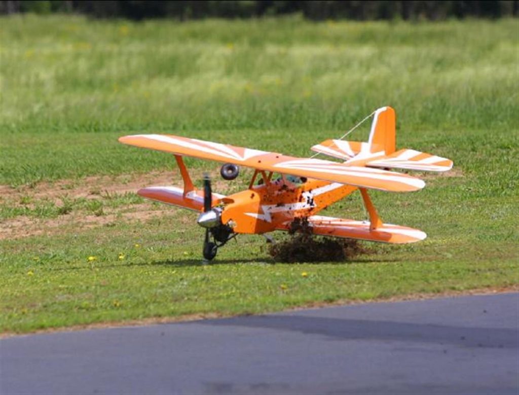
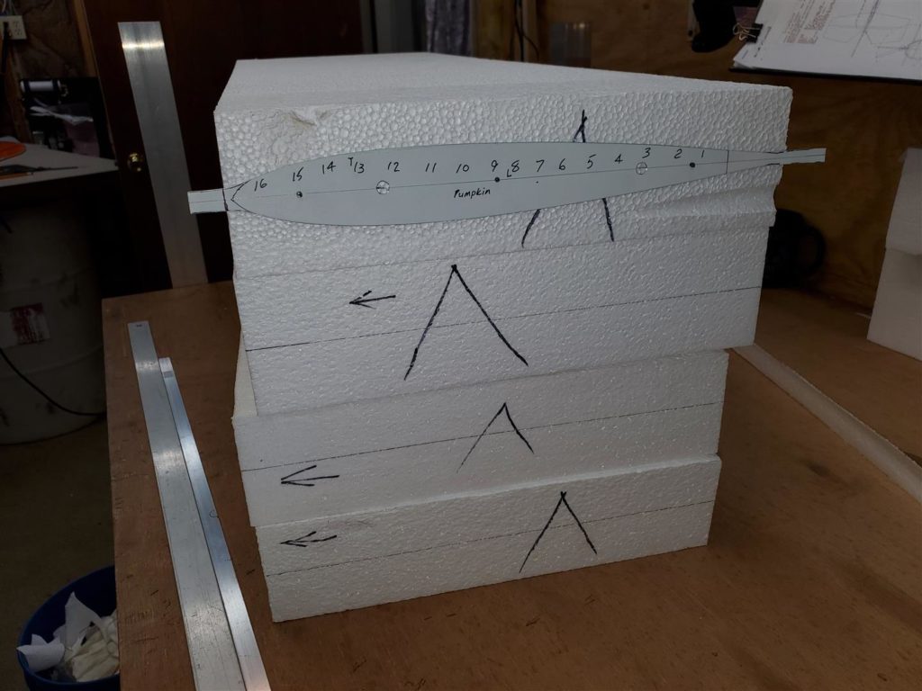
My second RC plane was a Sig Hog Biplane that I built from a kit. Later, I scaled it up to a 50cc version and built it from scratch. I called her the Pumpkin since she was orange and had a pumpkin head pilot. That plane really flew great! However, I followed the same construction methods used to build the smaller version and the plane came out pretty heavy. It still flew great but it was a brick.
When I saw Mike’s success building the Gnat series of planes, I knew I had to try to build a similar plane to Pumpkin Biplane. It would be so much lighter that it has to fly much better!
I also wanted to try the construction techniques Mike was using so I started acquiring or building the tools for making my own version of a BipeGnat. I needed a router table, router, vacuum press, foam wing drill, materials, templates and jigs etc. I already had a very old table saw and other normal shop tools.
I had a lot to learn and do! What follows are my efforts to make the first BipeGnat.
Fuselage Templates
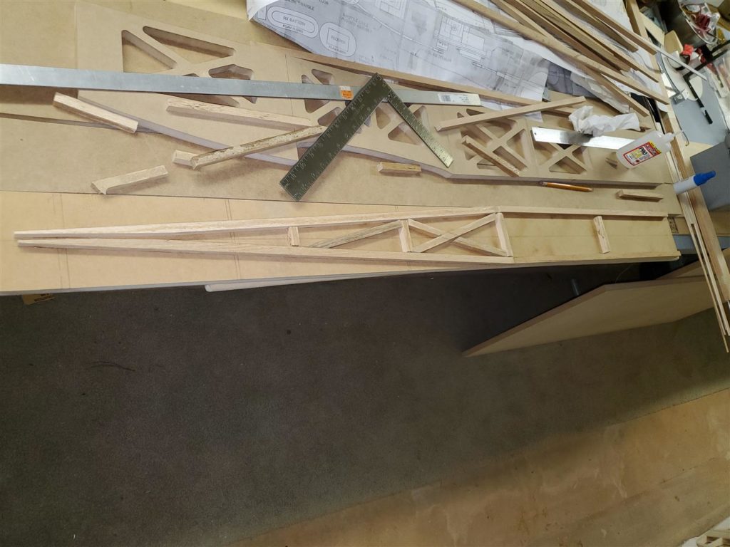
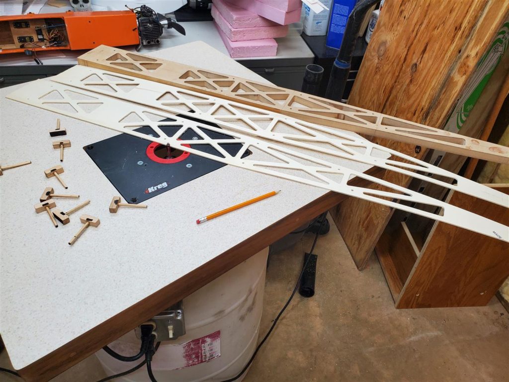
“Foam Core Wings” is meant to infer a complete airplane. The airplane needs not only foam core wings but also an airframe. In keeping with making very light and durable planes using relatively low tech methods, the airframes are constructed mostly of Liteply. Unnecessary material is removed from the components by using a router table to make them even lighter.
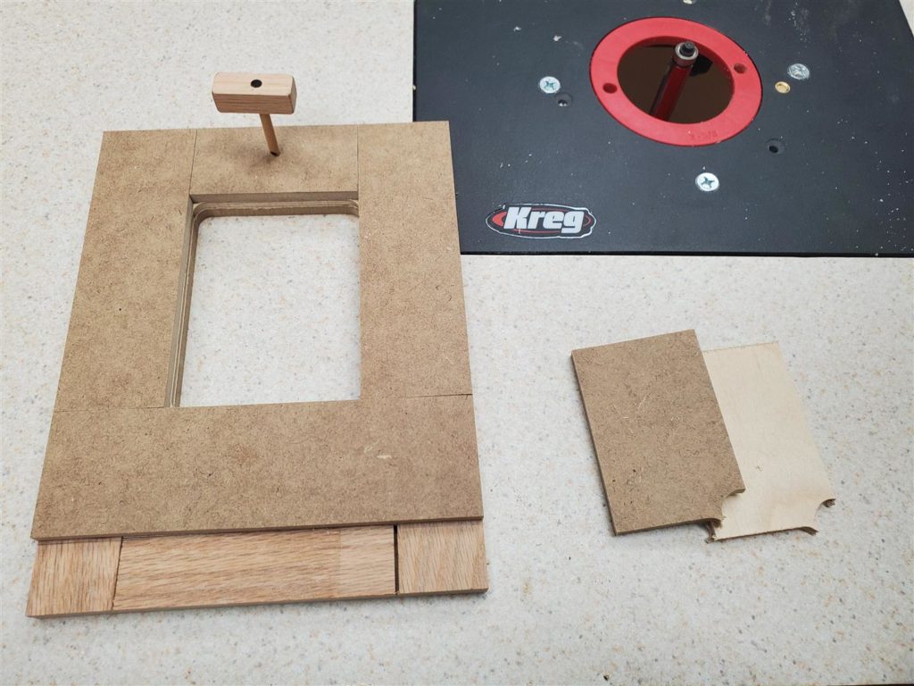
Templates are used to guide the router bits which results in a very light and durable fuselage. The templates are generally made of 1/4″, 1/2″ or 3/4″ MDF sheets. Hardwood such as oak is used to make some parts of the templates for router bit guides and sometimes spacers. 3/16″ dowels are used for alignment and holding pins to secure the materials that will be made into a part.
First make some router guides. 1/2″ x 1/2″ square oak sticks work well for the guides as long as they stay straight. The reason to use 1/2″ thick material is to allow for plenty of room for the router bit bearing to follow and set the width of the material to be left on the part. Thinner materials can be used but extra care must be taken to ensure the bearing runs along the guide. The oak guide sticks can be cut on a table saw.
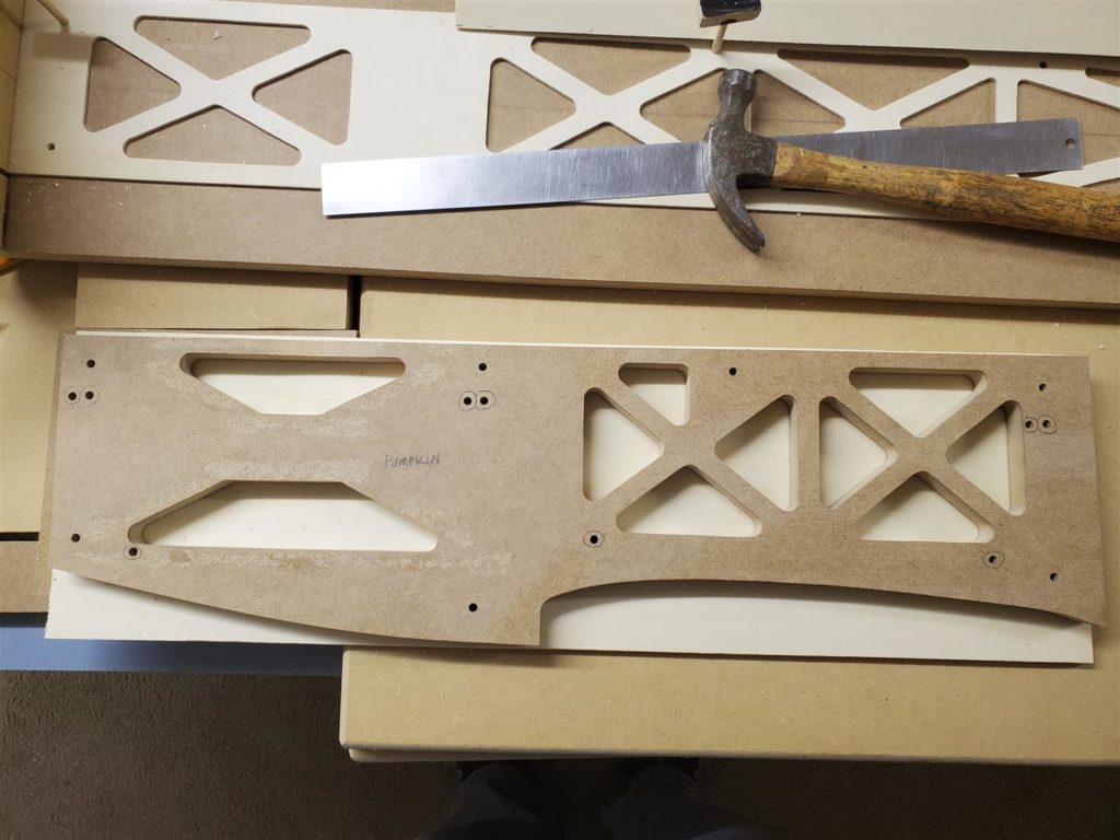
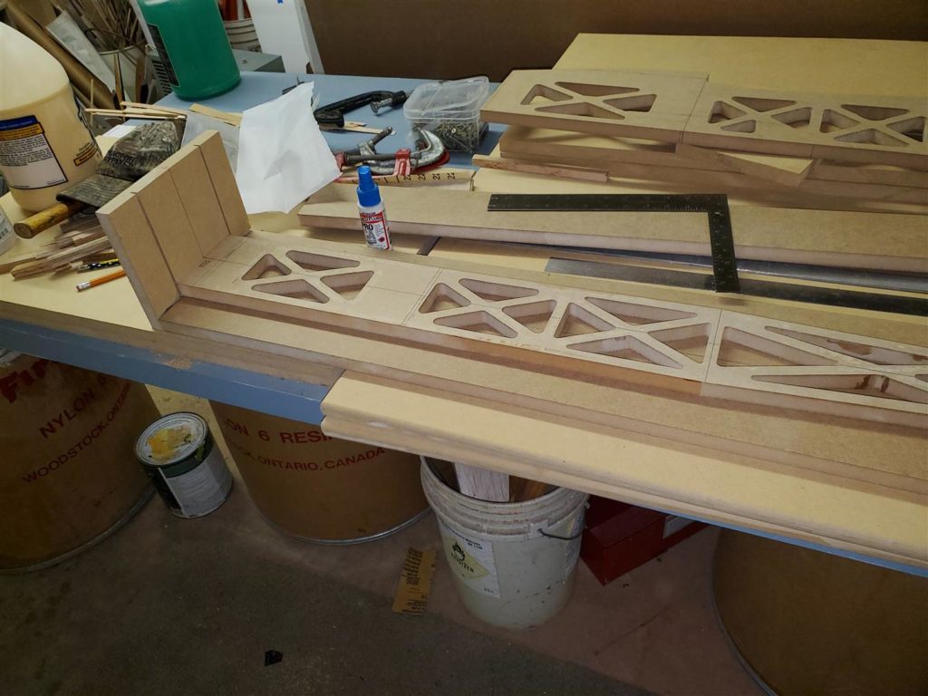
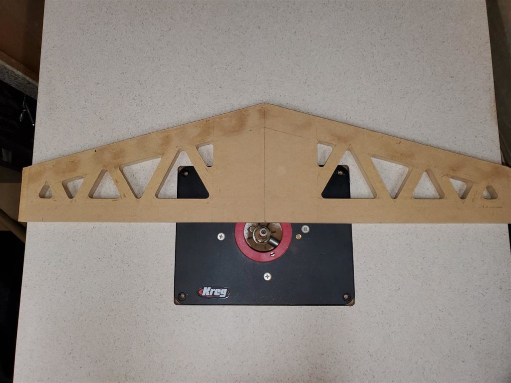
Next, a board wide and long enough to make the side profile of the fuselage is cut from 3/4″ MDF. The plan for the plane is used to draw the side profile onto the MDF. Add about 5/16″ at the firewall end to slide into a jig later. Cut the rough shape out with a band saw or jigsaw leaving extra outside to be routed off later. Use CA glue to attach router guide sticks exactly along the edges of the profile. Do not overdo the glue. All the guide sticks will be removed later.
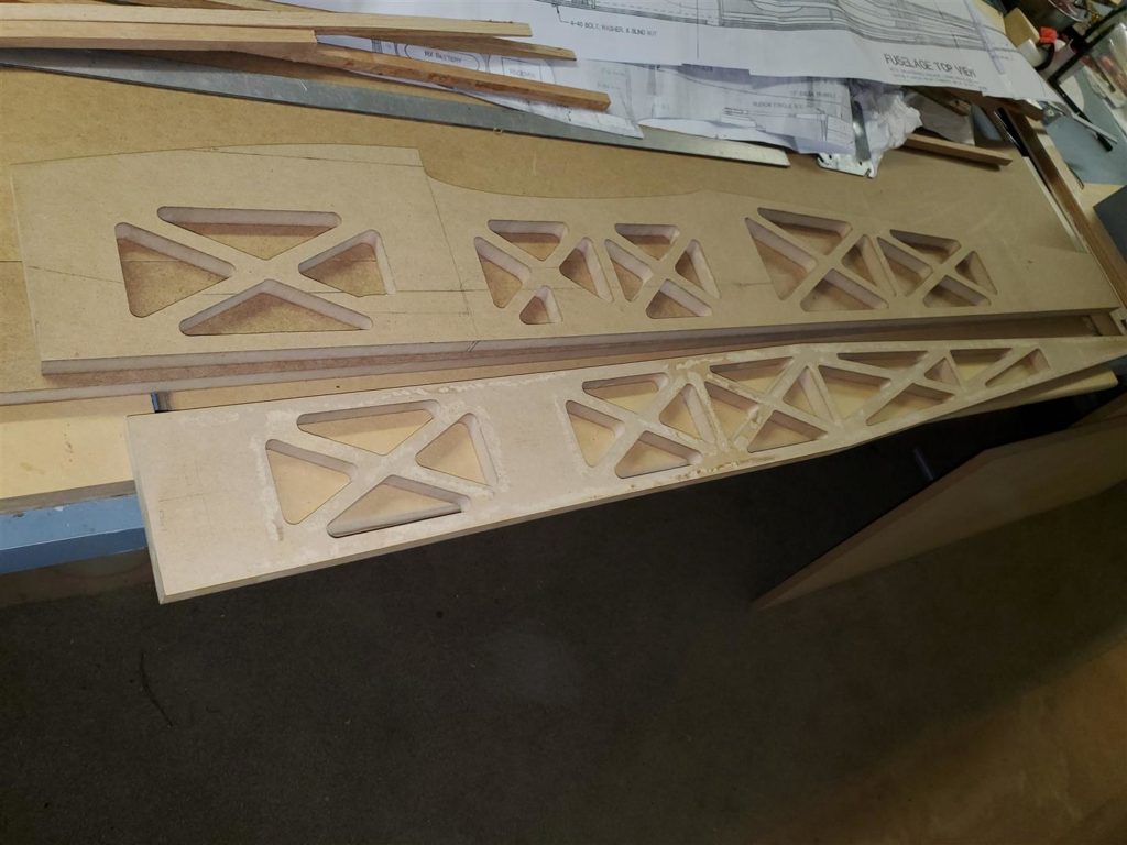
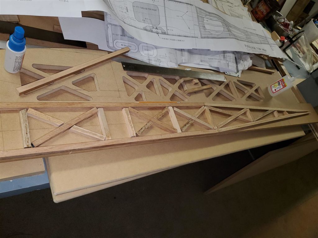
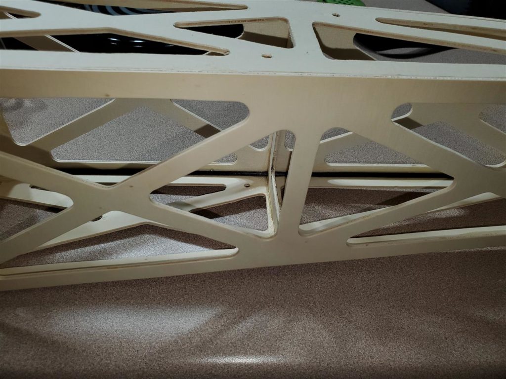
Now, decide where lightening holes can be made. BE CAREFUL not to remove material in areas that require extra strength. For example, fuselage former locations, the landing gear support area, firewall support areas, wing tube locations, strut attachments and the horizontal and vertical stabilizer attachments.
Triangle cutouts look fairly nice. Other shapes may also look nice. Decide how you want the part to look before laying out the areas to be removed. Symmetry is also something to consider. Again, BE CAREFUL to not remove too much but remove as much as reasonable to make the part light but strong.
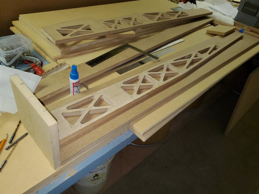
Normally, the formers will be starting points for guide strip placement. The former should be in the center of the width of the guide strip. Cut a piece of guide strip to fit between the top and bottom edge guide strips and glue it in place. Make sure it is properly located so the former will be centered. Also be sure to make the strip fit close enough to be sure the router bit bearing cannot drop into the gap. This will ensure nice rounded corners.
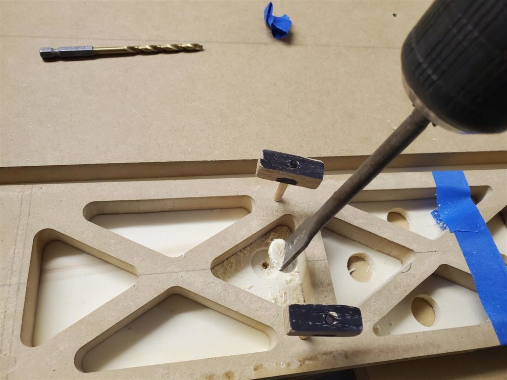
Once all the guide strips are installed, drill a hole for the router bit through the MDF in the areas where material is to be removed. A 5/8″ or 3/4″ drill bit works well for this. To avoid tear out on the bottom, place a scrap under the MDF while drilling. I use a paddle bit for this and stop about 2/3’s of the way through. Then I turn the part over and drill where the point of the paddle bit made a small hole. This results in a fairly clean hole every time.
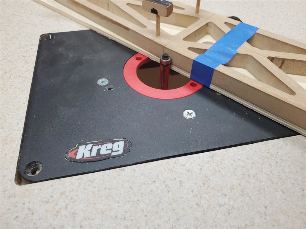
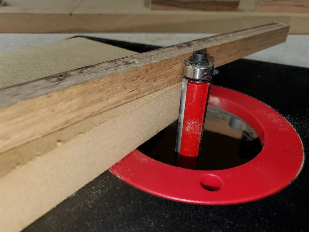
With all the holes drilled, it is time to set up the router in the router table. The 1/2″ x 2″ flush trim bit is used to remove the unwanted material. IMPORTANT…adjust the bit bearing to the proper depth to allow it to ride along the guide strips. Be sure the router cutting edges are extended high enough to make a clean cut next to the oak strips. Place the router into the table.
Routing of the template can now begin. A new bit spinning at the correct speed will cut through the material and not burn through it. If you are getting burned cuts, adjust the speed or if that does not work, get a sharp bit. A bit running too fast will leave brown burn marks on the MDF. Around 8,000 RPM seems about right for most bits. Carefully follow each guide strip around the area to be removed. Remove the waste MDF and clean up the edges before moving to the next area.
SAFETY FIRST!
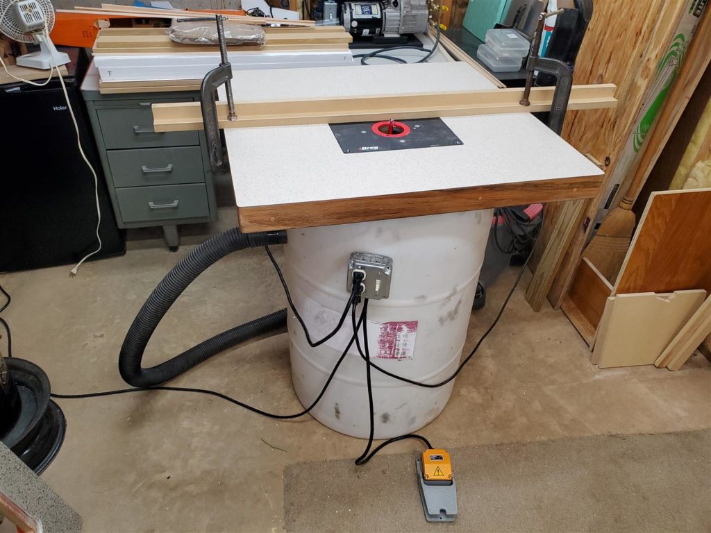
Using the router table can be hazardous. It has a cutting bit spinning at high speed that will easily remove flesh and bone. You must be careful not to let that happen. Keep both hands on the part being routed with a firm grip and body parts away from the bit. That is why there is a foot switch on my router so I do not have to remove one hand to turn it off. I also turn the router off and wait for the bit to stop to move to the next area to be routed to avoid injury. Also, you may inadvertently nick the part while trying to move it with the router bit still spinning. Foot switches are a matter of preference. Some guys love them and others don’t. Mike cant seem to get used to his and avoids using it. I feel far more secure with mine.
CAUTION! If a waste part is cut completely loose with the router bit, it can become a projectile or cause a jam that can unexpectedly and powerfully move the whole part being routed. Stop before reaching the point where the waste becomes a loose part. Turn the router off and wait for the bit to stop. Break out the waste piece. Then continue routing to clean up the area. There may be other hazards so do the routing at your own risk!
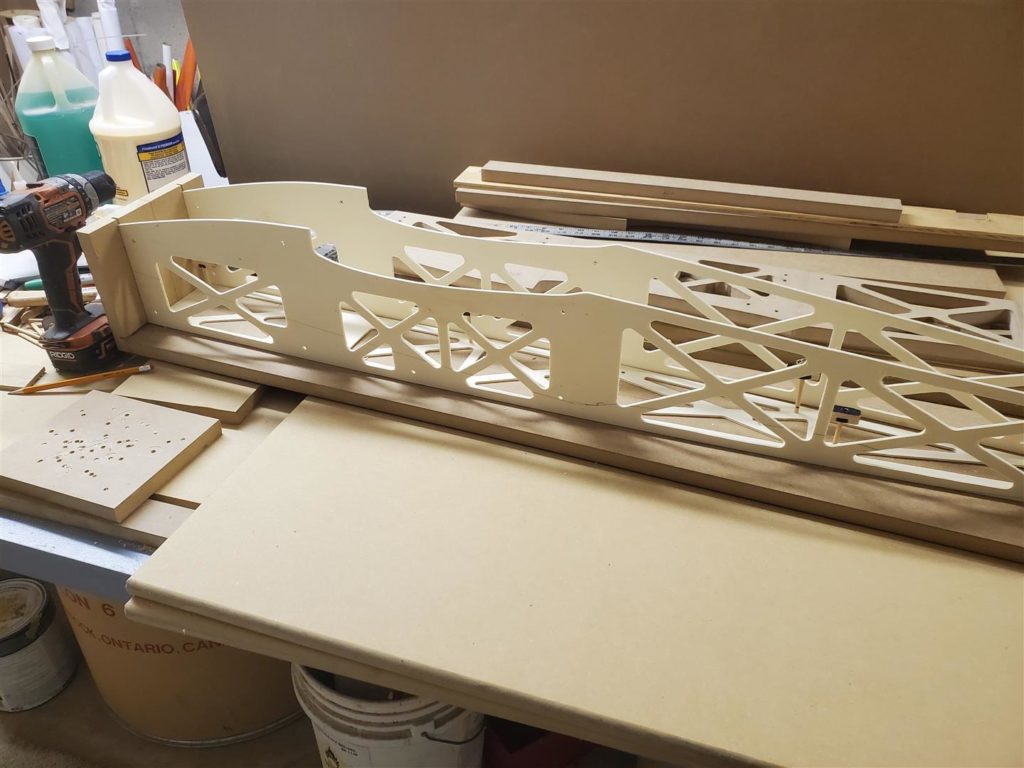
The outer strips were placed flush to the outside edge of the part outline. So now the outside edge can be flush routed for final shaping of the template. Again be careful of waste parts if any so they do not become projectiles.
A wood chisel and small hammer can be used to remove the oak guide strips from the template. There will be some tear out. Hopefully, it will not be a lot. The only thing this will affect is how the template looks unless it is excessive and would affect the bearing riding smoothly. This is partly why we use the 3/4″ MDF and try not to overdo the CA glue. Mike likes his looking nice (OCD) so he runs the templates through a surface sander to smooth them out. I just sand the rough spots and leave it at that.
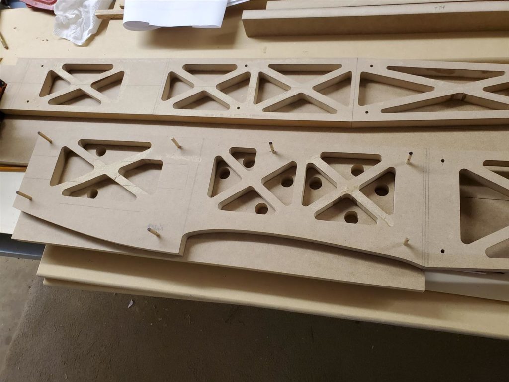
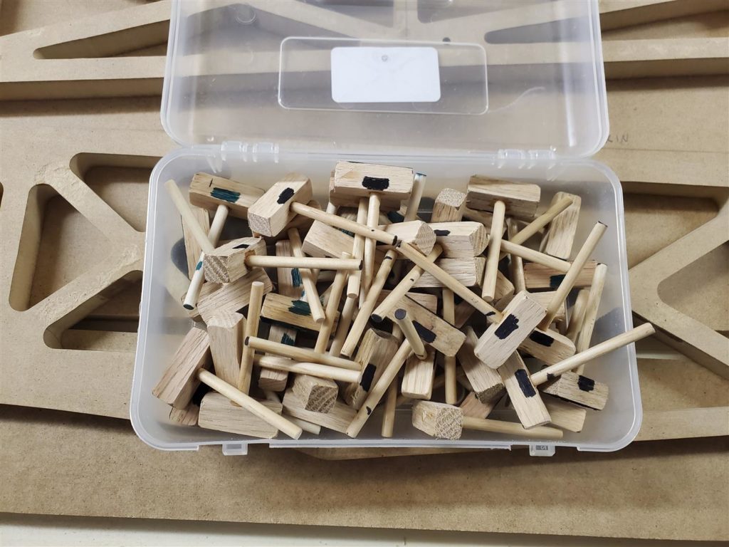
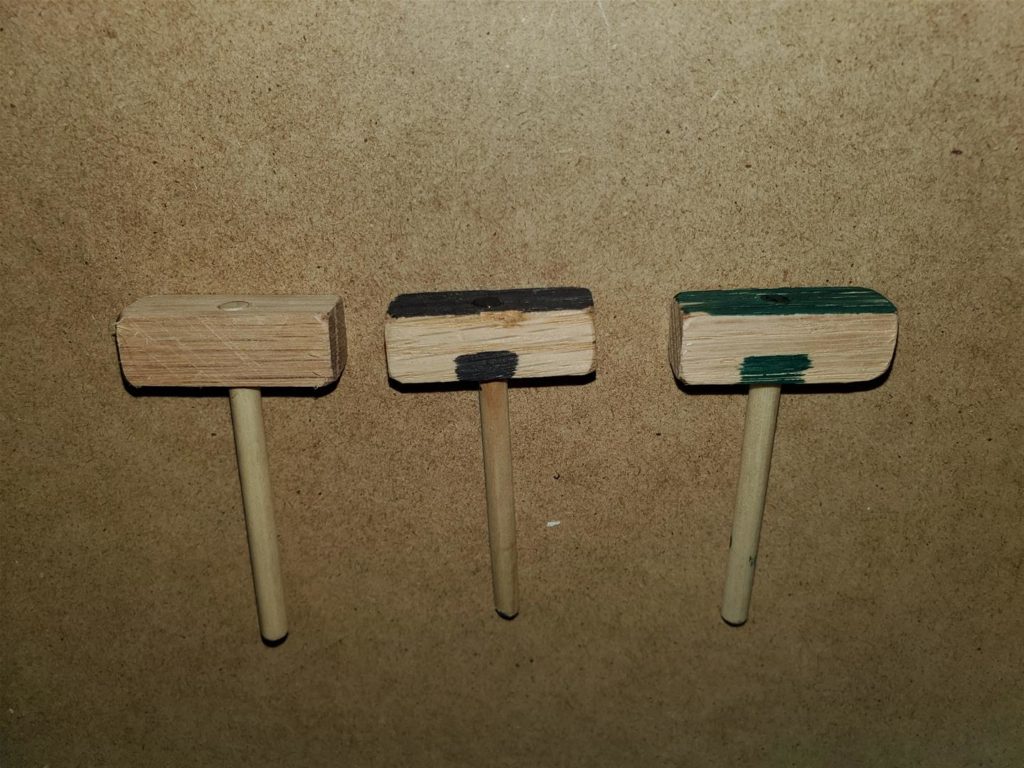
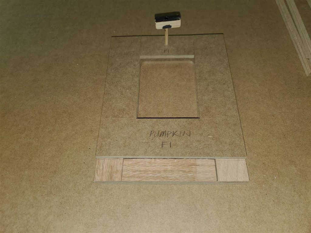
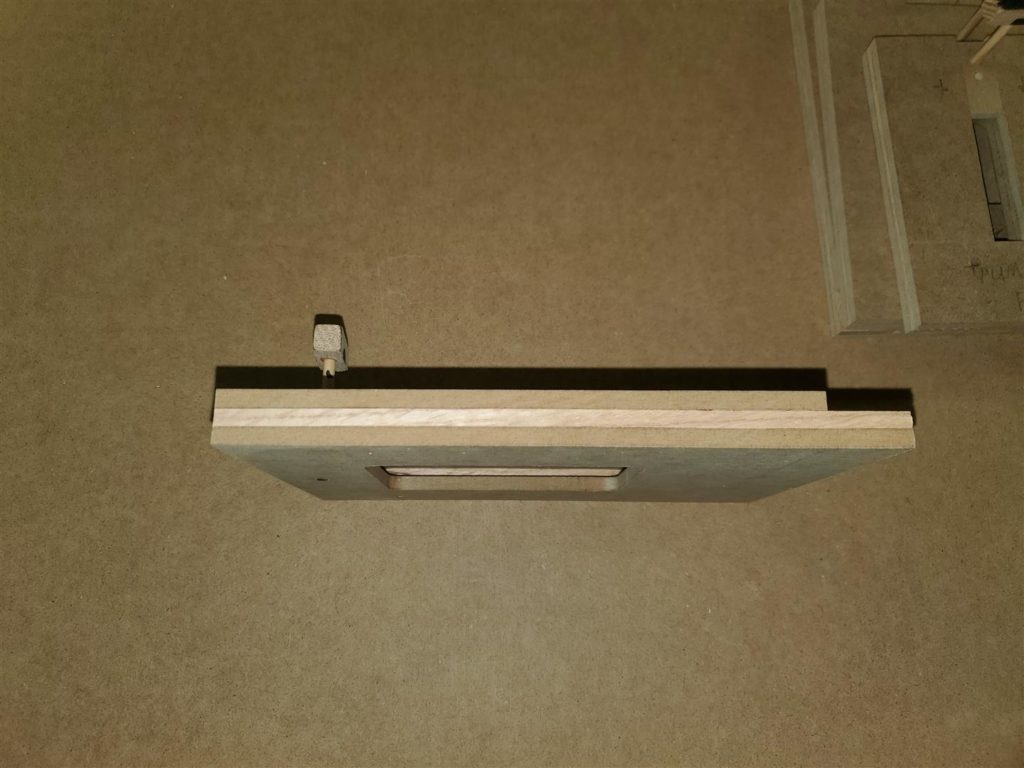
Now make some alignment pins out of the 3/16″ dowels. First test drill a scrap piece of MDF with a 3/16″ drill. Test fit the 3/16″ dowels to be sure they make a nice snug fit. If they are too loose the part will move around. My numbered drill set is where I had to go to find a perfect sized bit to drill the alignment pin holes. During testing, I found that some of the dowels fit differently in the same size hole. So, I made several size alignment pins. Some are very tight, some are tight and some are perfect fit. The very tight ones can be used later if the holes get too loose. Cut some 1″ pieces of the oak guide strips to make a head for the alignment pins. Drill a hole in the center of each head and glue a section of dowel into the holes. If you make several sizes, color code them for easy identification.
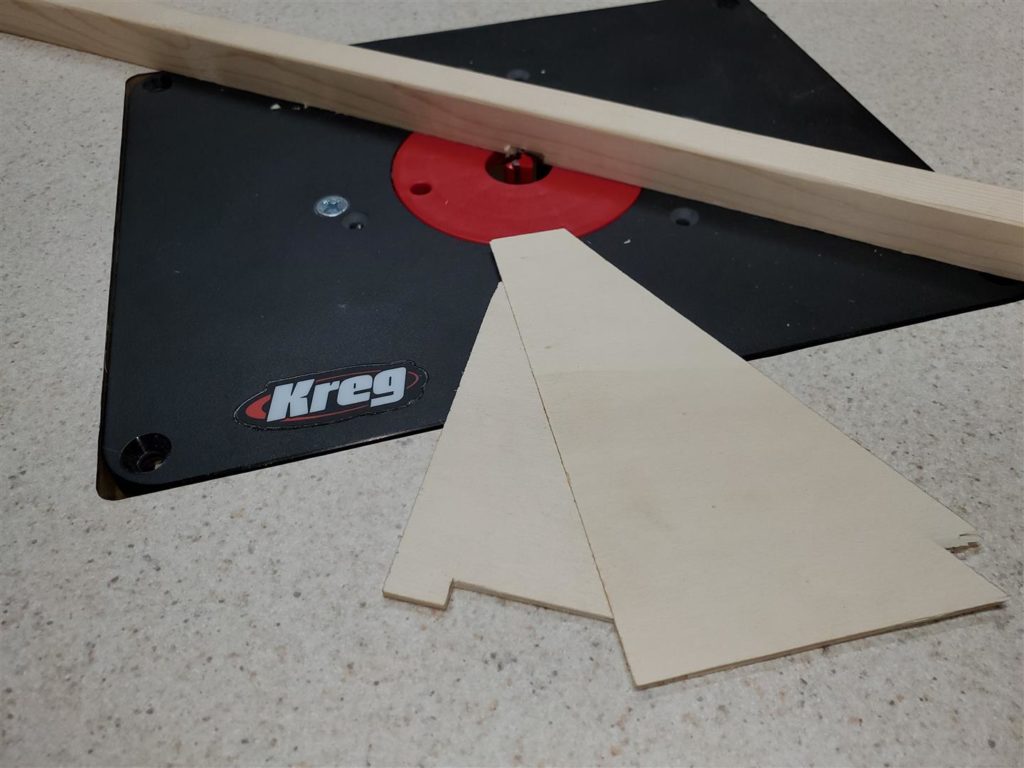
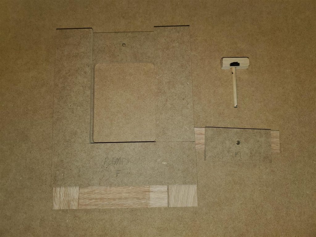
Finally, select locations to drill alignment holes into the template. These same holes will be drilled in the parts made by the template. So choose locations that are suitable and do not interfere with formers, wing tubes and etc. Stay at least 1/2 inch from where you believe a form will be positioned later. Otherwise, CA will dribble from the alignment pin hole when we glue the former in place. Notice in the photo on the right where the alignment pin hole is located with respect to the former location.
Label your fuselage templates so when you have made several you can identify it for which plane. Make templates for all the parts needed for the airframes outside surfaces. Storage should be on a flat surface, or hanging to ensure they stay flat and straight.
Template Use
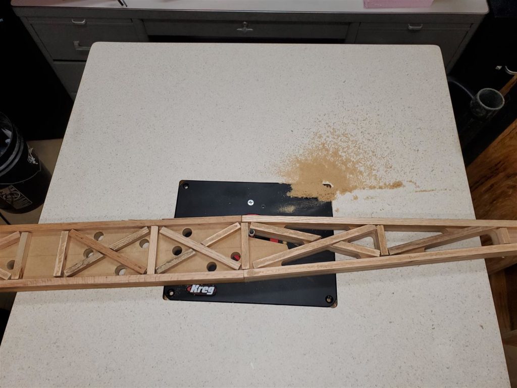
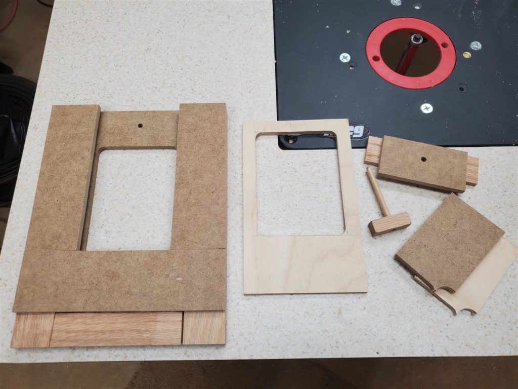
Using the templates is “Super Easy”. Cut a piece of liteply of adequate size. If two parts are needed, both can be made at the same time. Cutting two parts at a time seems optimum. Three or four seems to work the router harder and really isn’t worth it.
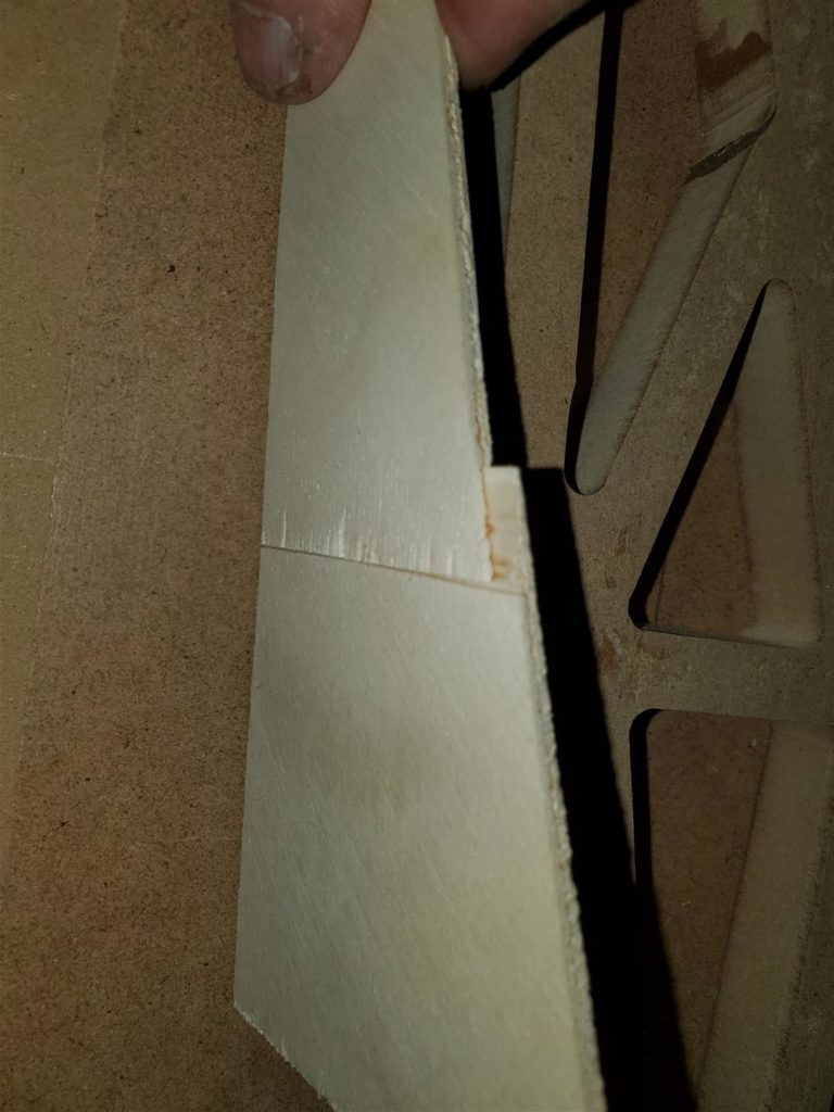
Most LitePly comes in 1’ x 4′ pieces. That was not long enough for the part needed below. So using a fence on the router table and a 3/4″ plunge bit set to half the thickness of the LitePly, a test scarf joint was made. The two pieces were glued together with CA glue.
While this joint is not as strong as the rest of the liteply section, the area the joint is to be placed in will be part of a box where the horizontal and vertical stabilizer will be attached. Also, no lightening holes will be made in this area. No backer piece was use here but could be added if more strength is needed. So the lite ply piece was extended a few inches using this method. Of course, the best way to avoid this is to buy larger pieces of LitePly. After doing this, I began buying LitePly in 4’x8′ sheets. It’s far cheaper that way too.
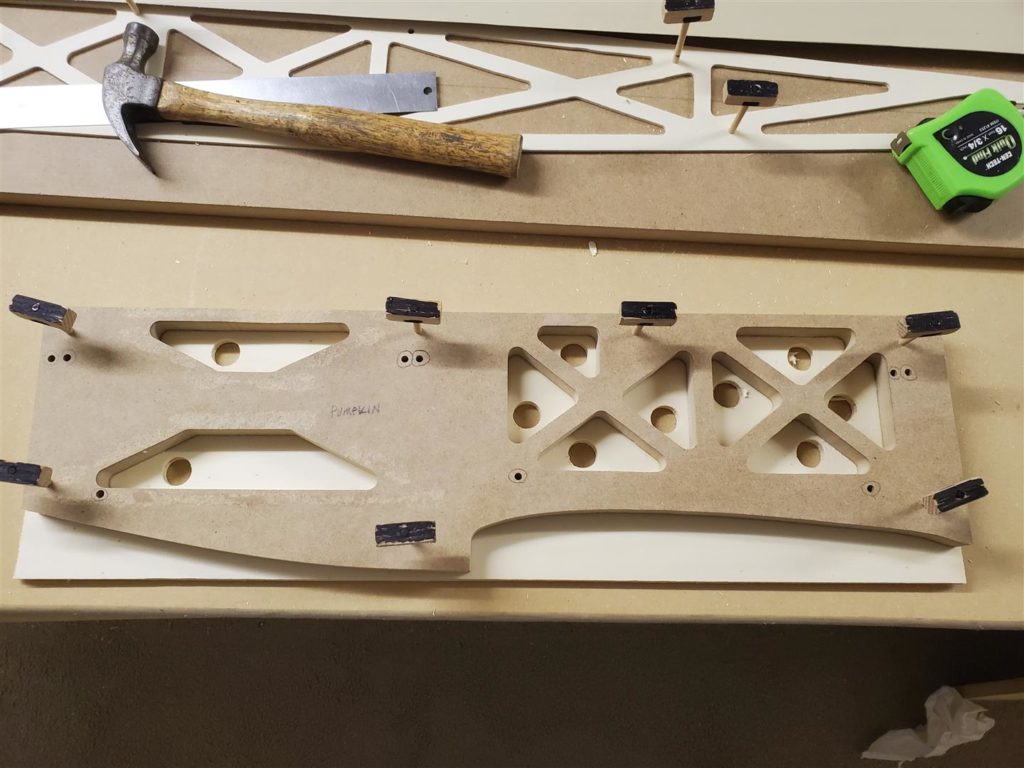
Place the template over the liteply pieces. Use a hand drill and the same bit used for the alignment pin holes to drill holes in the liteply. Install an alignment pin after each hole is drilled to keep the part secure.
A few wraps of everything with blue painters tape will help keep the liteply firmly pressed to the template.
Drill holes for the router bit in each area to be routed. If you use a paddle bit drill partially through from the top side and turn the part over to drill through from the bottom side to avoid tear out.
BE SURE to properly align the height of the router bit bearing to ride on the router template. If you forget this step, you may damage the parts and templates. Use the same cautions when routing out the waste. Stop and remove the waste part before cutting it loose.
That is it! Be careful and have fun routing. As Mike likes to say, “This is ADDICTIVE”!
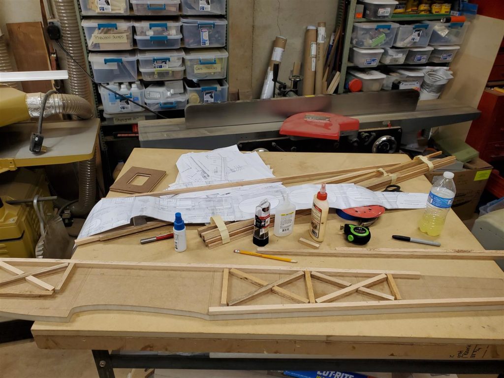
Fuselage Jig
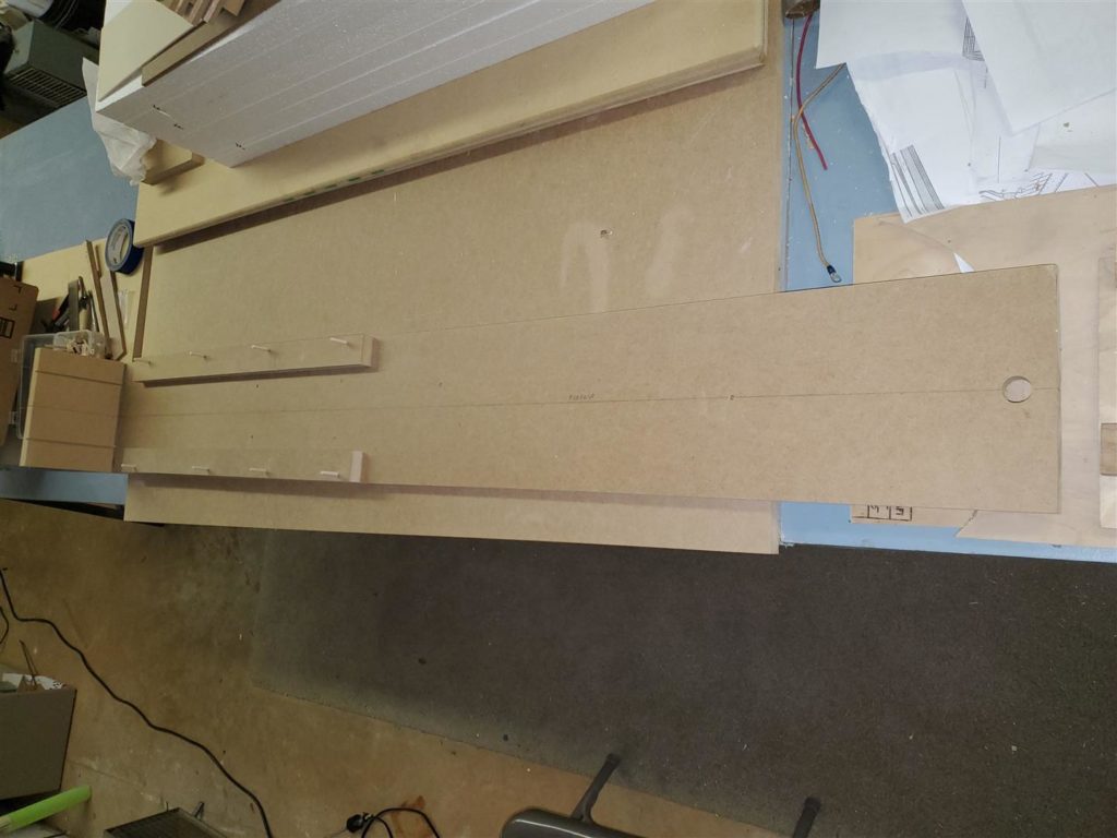
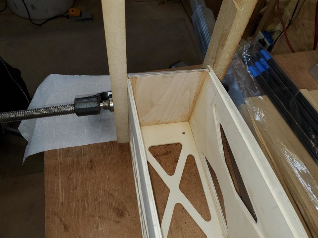
After cutting the sides to build a fuselage, a jig can be used to hold the parts straight and squarely while they are glued together. Using a jig speeds up the construction process. Making a jig requires a little time but the final product being straight and square more than offsets the investment of time.
This jig is constructed of a flat piece of 3/4″ MDF. The base should be wide enough to allow some 2″ wide MDF strips along each side of the fuselage. 3/16″ dowels are used for holding the bottom or top firmly to the base.
The base piece should be a little longer than the fuselage and have both ends cut squarely to its sides. Draw a centerline down the length of the base piece. Be sure to get everything square here to achieve professional results later.
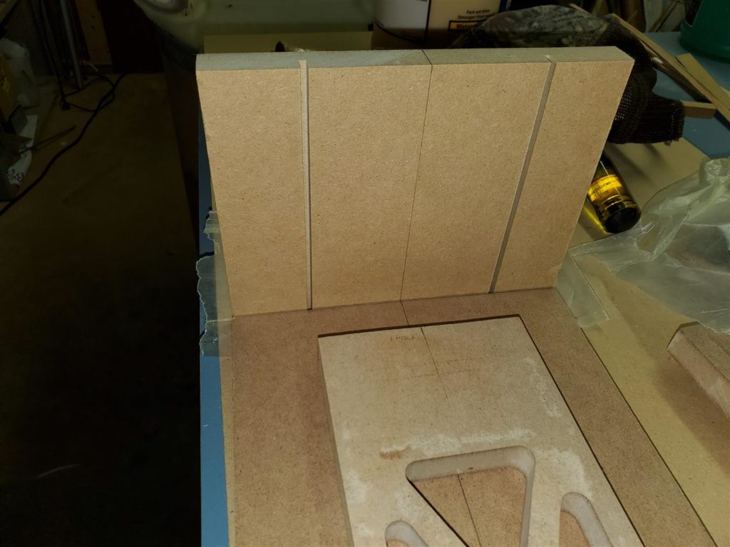
The end piece of the fuselage is made of the same width as the base and tall enough to allow it to be attached to the base vertically. Two slots are cut into the end piece to accept the front edges of the fuselage. The table saw blade is set to the thickness of the firewall plus 1/8″. The slots are cut on the table saw spaced to exactly the width of the top and bottom templates. Some fuselages are built with the bottom on the jig base and some are built turned upside down. Choose the side that is flattest.
The end piece is attached to the front of the base with glue and wood screws. MDF will split easily if a screw is inserted without the proper size pilot hole. So be careful and drill and countersink the screw holes.
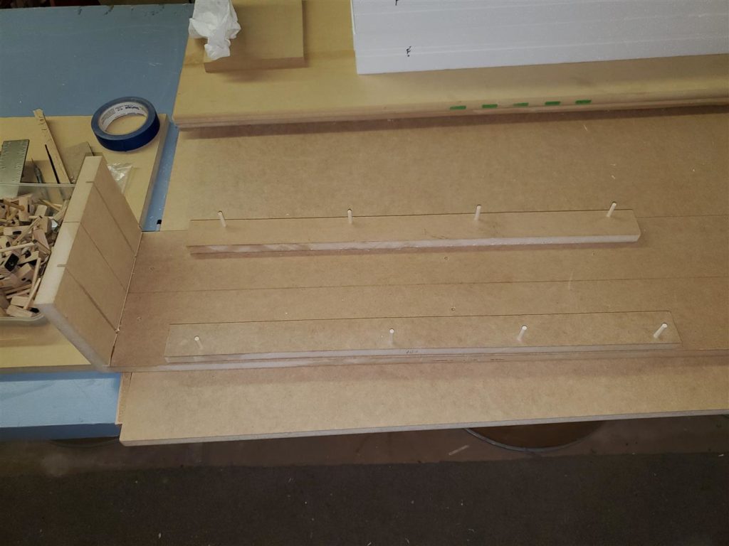
The top fuselage template is used to set where the side will align on the jig. The peg holes are then drilled in the template. Then the template is clamped to the jig and the peg holes are drilled into the jig.
Insert the two fuselage sides into the front slots. Lay in the top (or bottom) template onto the base between the two sides.
Cut two strips of 3/4″ MDF to 2″ wide about 2″ or 3″ longer than the length of the fuselage before it begins to taper. These are then placed firmly but squarely against the sides of the fuselage to press them against the part laying in between them. They are then glued or pegged into place. My jig uses the same 3/16″ dowels used for the fuselage jig to hold the MDF strips in place. If you use pegs it is important that the pegs are tight in the drilled holes. It is also very important to make sure the fuselage sides are kept square to the front of the jig before gluing or pegging the MDF strips to the base. Use the centerline to assist in keeping everything square.
The top (or bottom) fuselage must be held securely onto the base while gluing. Since there are already peg holes in the part, the existing peg holes are drilled into the MDF. Lay the top (or bottom) template onto the base and use the existing peg holes as a drilling guide. Be careful to properly align the template. Do not allow the part to move while drilling by inserting a peg into each hole as they are drilled. Check that the template stays properly aligned on the centerline as each hole is drilled.
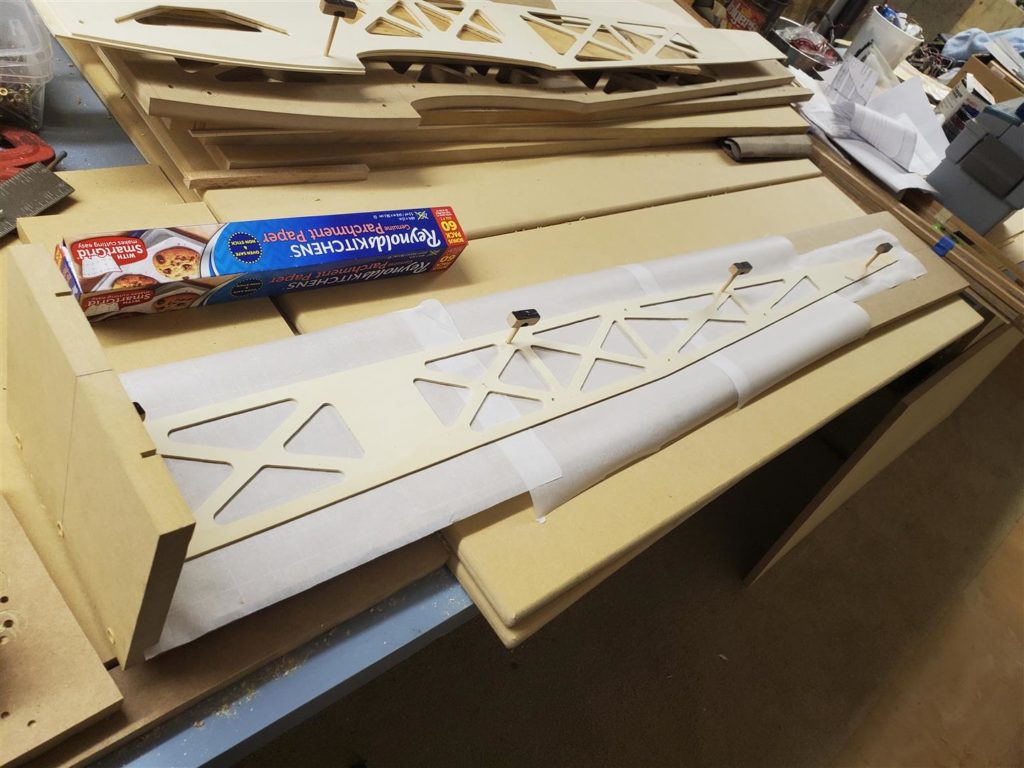
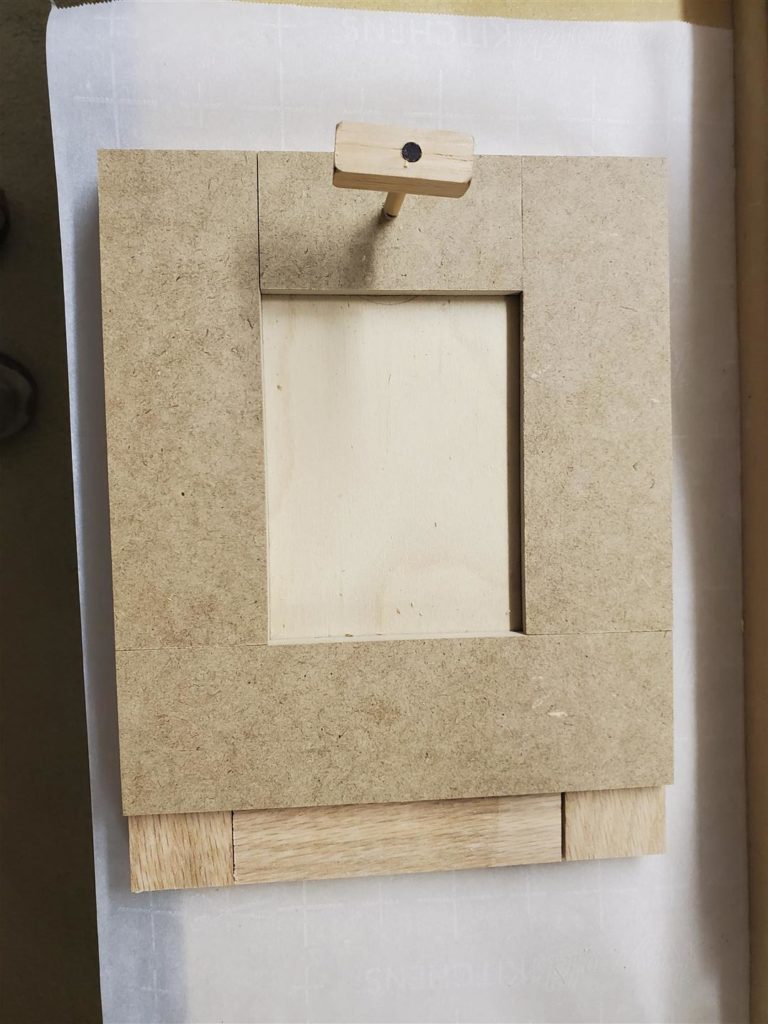
Test fit the parts on the jig. Make any adjustments before any gluing begins. The parchment paper was test fitted here too. It will protect the jig from glue run out. It did not affect fitment.
Former Templates
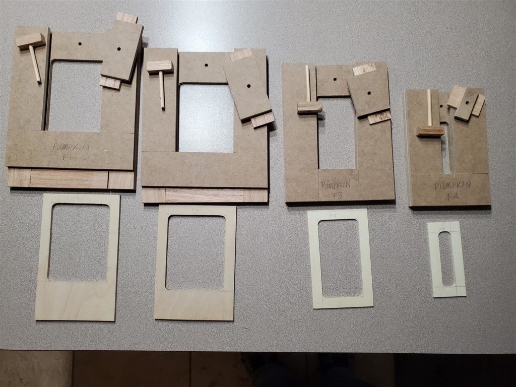
The next step is to make some former templates.
Former templates are used to make the fuselage formers. They are necessary to securely hold the formers while the waste parts are removed.
Former templates are constructed of 1/4″ MDF, oak strips and 3/16″ dowel pins. They are sized to match each former size. Close fit is required to hold the part firmly. But the part must also slide easily in and out of the template.
First careful measurement of the width and height of the template is laid out onto a piece of 1/8″ Liteply or thicker plywood if needed. It is imperative that the when cutting these lines the sides are perfectly square and fit firmly into the fuselage. Starting a small amount oversized allows the former to be trimmed slowly for a tight fit. Do not forget to allow for the formers to be 1/4″ shorter than the sides to allow the top and bottom to fit perfectly into the sides.
Next a piece of 1/4″ MDF is cut to be about 2″ larger all around than the fuselage former being made.
The former is centered onto the MDF. Strips of oak cut just thicker than plywood former thickness and about 1″ wide are cut on the table saw. First an oak strip is glued along the bottom edge of the MDF but touching the bottom edge of the plywood former. Side strips of oak are then glued onto the MDF along the sides of the plywood former. Be sure the part will slide in and out but fit snuggly before gluing the second side on. The side oak strips are also long enough to extend all the way across the top edge of the MDF. Leave the top oak piece off for the time being. It is going to become a removable door. Do not worry about how much the outside edges of the template are not aligned. The whole template will be squared up at the end.
The router flush trim bit bearing will ride along guide strips of 1/4″ MDF. These strips are cut about 2″ wide and glued onto the oak strips leaving the area to be removed open. They set the size lightening hole to be made into the fuselage formers.
The bottom and side 2″ wide MDF guides are glued on first. Again the side pieces of MDF are long enough to extend all the way across the top edge of the oak strips. They must be placed carefully to size the lightening hole to be routed.
Former Template Use
Insert the plywood former into the appropriate template. Drill a hole for the router bit.
CAUTION! These templates are small and require a firm hand to use. Be very careful to avoid injury or mistakes.
Adjust the router bit bearing height to ride on the 1/4″ MDF guide strips and make the parts.
Now Fuselage gluing can begin.
Fuselage Jig Use
Fuselage Jig Use:
With all the formers cut, the fuselage gluing can begin. The jig will be used to hold everything in place. CA glue will be used to tack everything together. Use of too much glue can glue the fuselage to the jig if the glue runs out. Parchment paper can help you avoid that.
First install the top or bottom onto the jig base securing it with dowels. Install the two sides into the front end slots. Be sure they are fully in the slots and that they are resting on the MDF base.
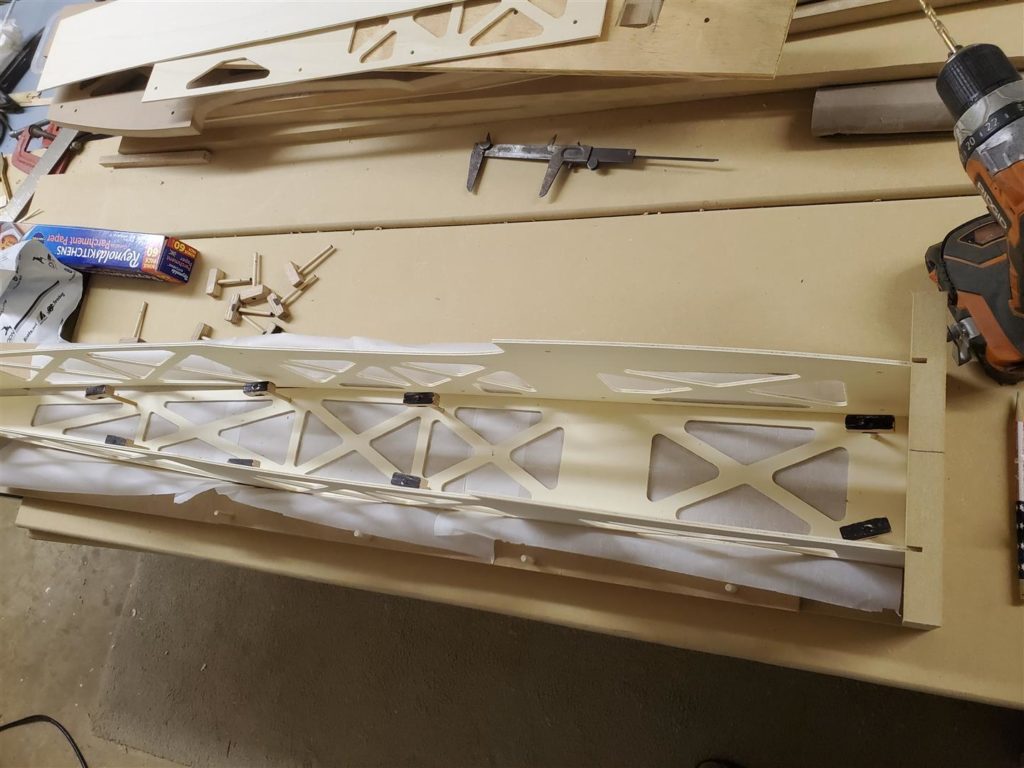
Now the formers can be glued in their proper locations. Use a square to keep them vertical while the glue sets. At the place the fuselage sides begin to taper, use some wedges to force the bends to be tight bends.
Tack glue strategic locations to keep everything together.
Now the bottom rear section is tacked on.
CA will be dripped into the corners of each piece later to finish the gluing. The firewall is glued in later with epoxy and aluminum angle supports.
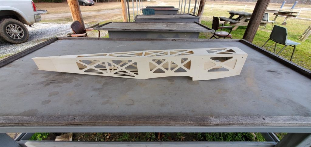
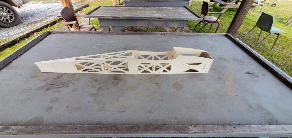
Fuselage Build
With the templates made and parts cut out, building the fuselage with the jig is “Super Easy”. The jig holds the sides nice and square resulting in a very professional fuselage. See the Fuselage Jig Use posting on the Fuselage Jig post.
http://mostlymiata.com/fuselage-jig/
The firewall can be installed with the fuselage removed from the jig. It is glued in using 30 minute epoxy. Epoxy is applied to both parts and is clamped firmly in place while the epoxy cures.
Now that the fuselage is formed and tacked together, it will need to be permanently glued. Strategically drip medium CA into all the corners along all the parts letting it run along the corners. Do not breathe the fumes. Do this with proper ventilation and wear a proper respirator. CA fumes will hurt you!
The fuselage will need extra support and strength in a few areas.
The rear section of the fuse will be reinforced with 3mm carbon fiber tubes or rods. They are installed along the bottom side corners from the rear of the fuselage to the former where the fuselage starts to taper.
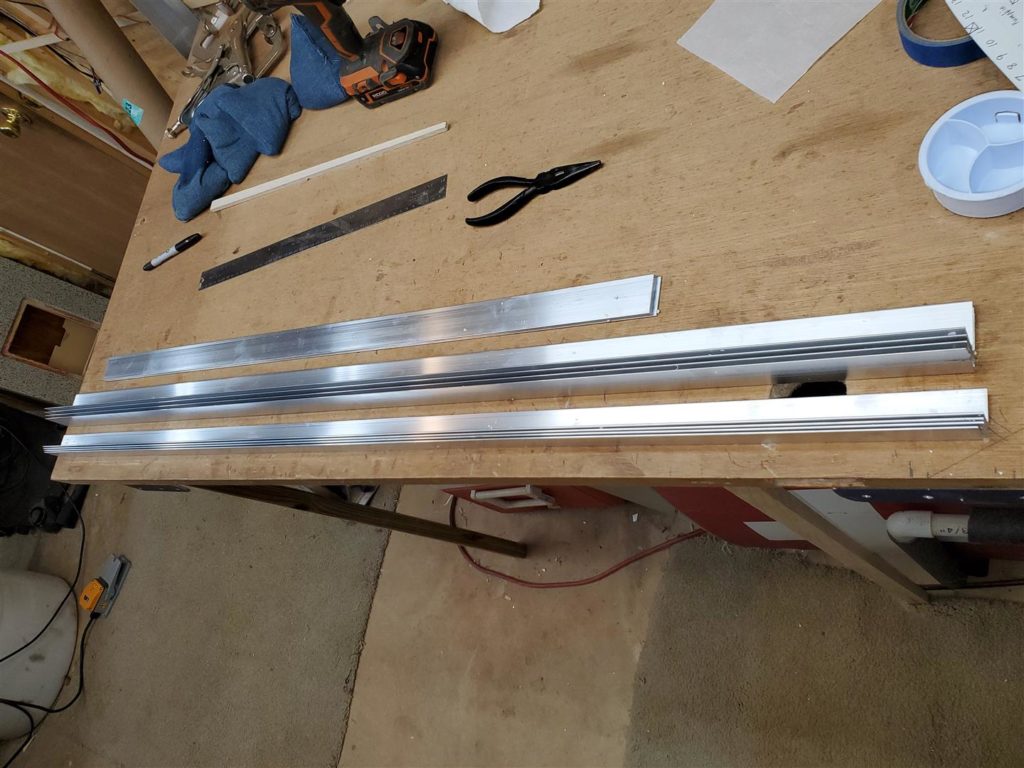
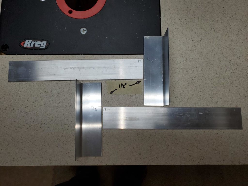
The firewall and landing gear areas will also need reinforcement. 1/16″ x 1.5″ aluminum angle and flat stock are used to reinforce the firewall. 1/16″ x 1″ aluminum angle is used to reinforce the bottom for the landing gear attachments. These materials are available at McMaster-Carr. The part numbers for the sections used here are:
Multipurpose 6061 Aluminum 90 Degree Angle with Round Edge, 1/16″ Thickness, 1″ Outside Height, 4′ Long
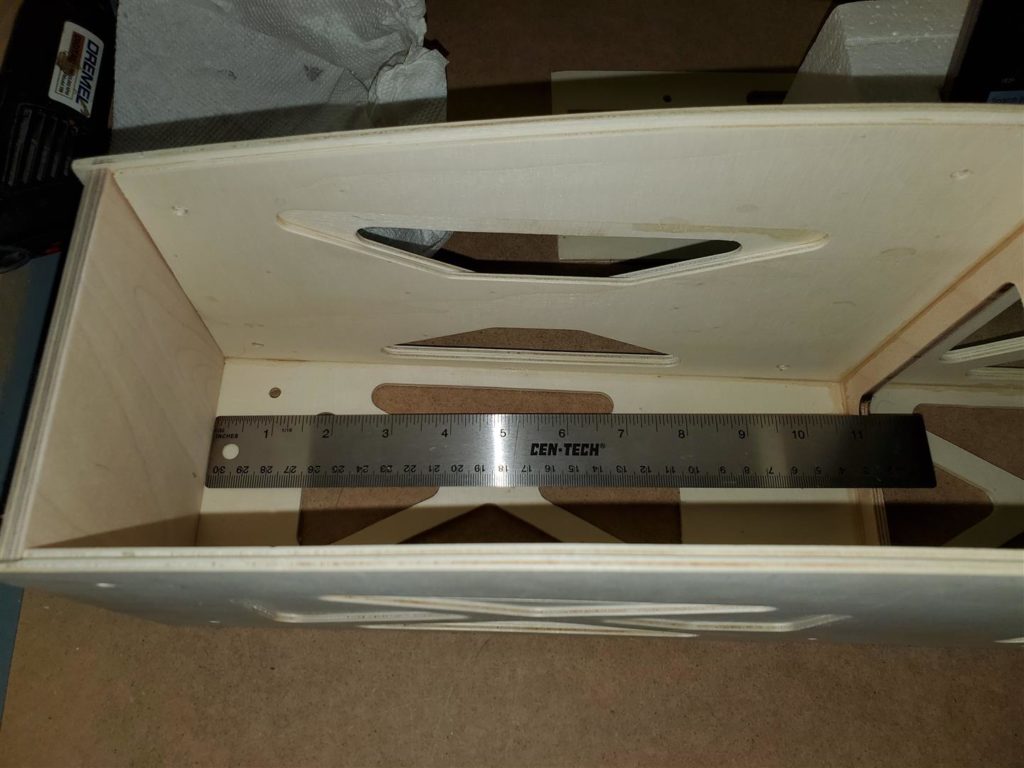
Measure for cut lenghts.
The firewall angle supports are about 1/4″ shorter than the firewall and the flat stock runs from the angle to the first former.
The aluminum supports are glued with 30 minute epoxy to the inside of the fuselage.
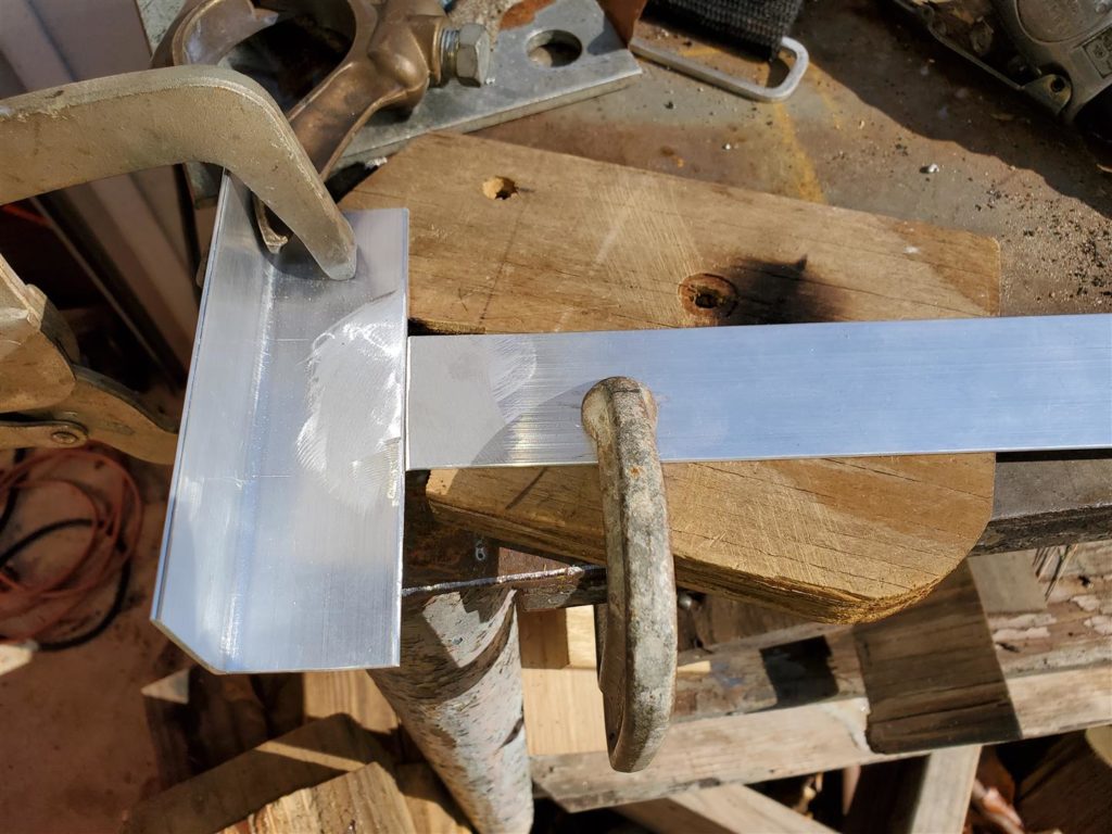
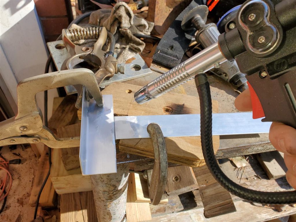
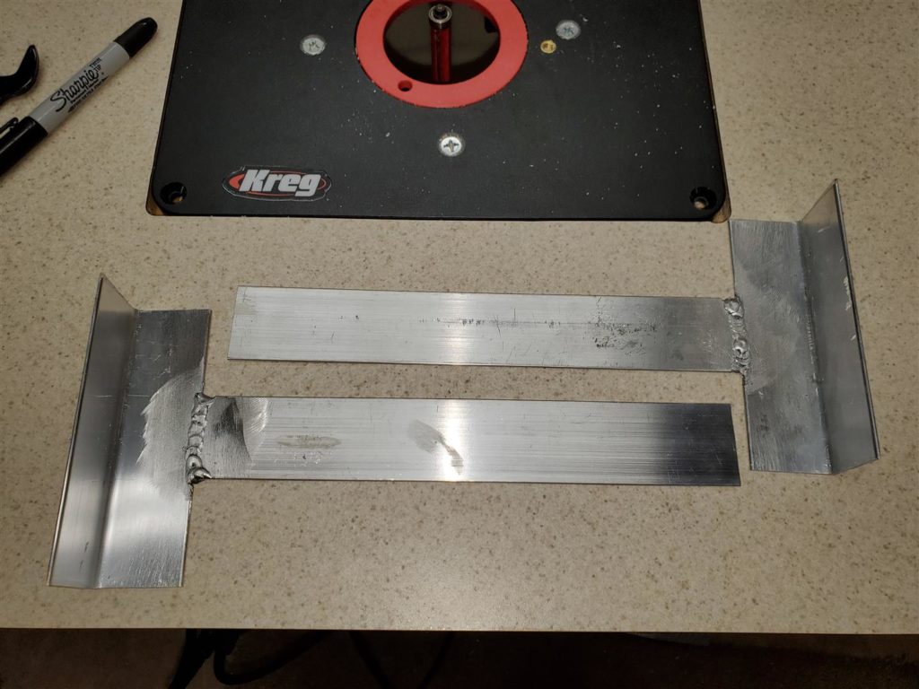
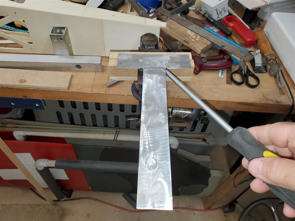
The firewall angle and flat support pieces are welded together or brazed together. A MIG welder with the proper setup can be used to weld them. Brazing them together requires some Alumaweld rods and a map gas torch.
I own a welder so that was easiest for me. Mike uses Alumiweld rods which are obtained on line and are very inexpensive and easy to use. See his video on using those rods. See the link that I have placed below for how Mike does it.
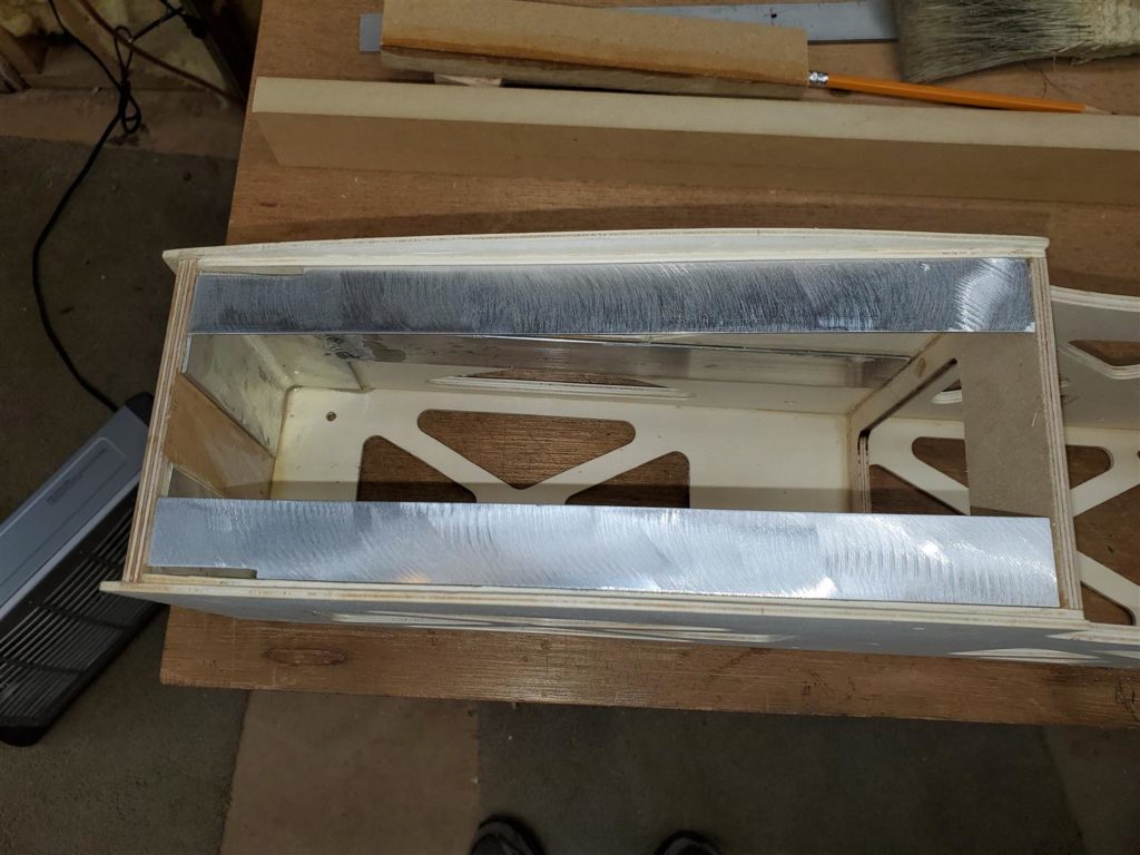
Welding or brazing requires the metal to be clean and bright. Oxidation and dirt will keep both from working. A dedicated stainless steel brush for use only on aluminum can be used to remove the oxidation. This firewall has a 1.5 degree down thrust angle so for the parts to fit the angle must be included in the support pieces. Care must be taken to make a right and left piece to be sure the angles are correct for each side.
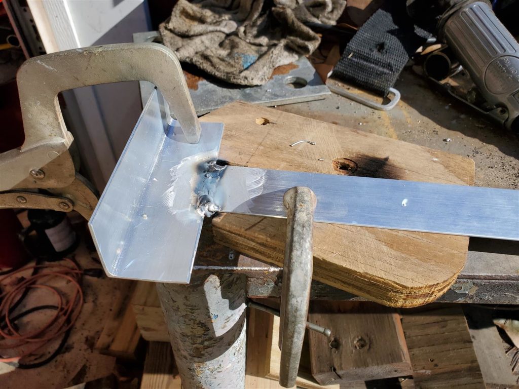
Here are some pictures of the welding process.
Here is a quick video on how to braze them.
For detailed instruction on how to use the Alumaweld process, see the first 12 minutes of this video on Fuselage Construction.
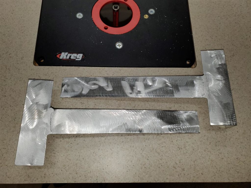
The weld on the side to be glued to the wood is ground flat. The support parts are then roughed up to ensure a good mechanical bond with the epoxy.
Test fit them first.
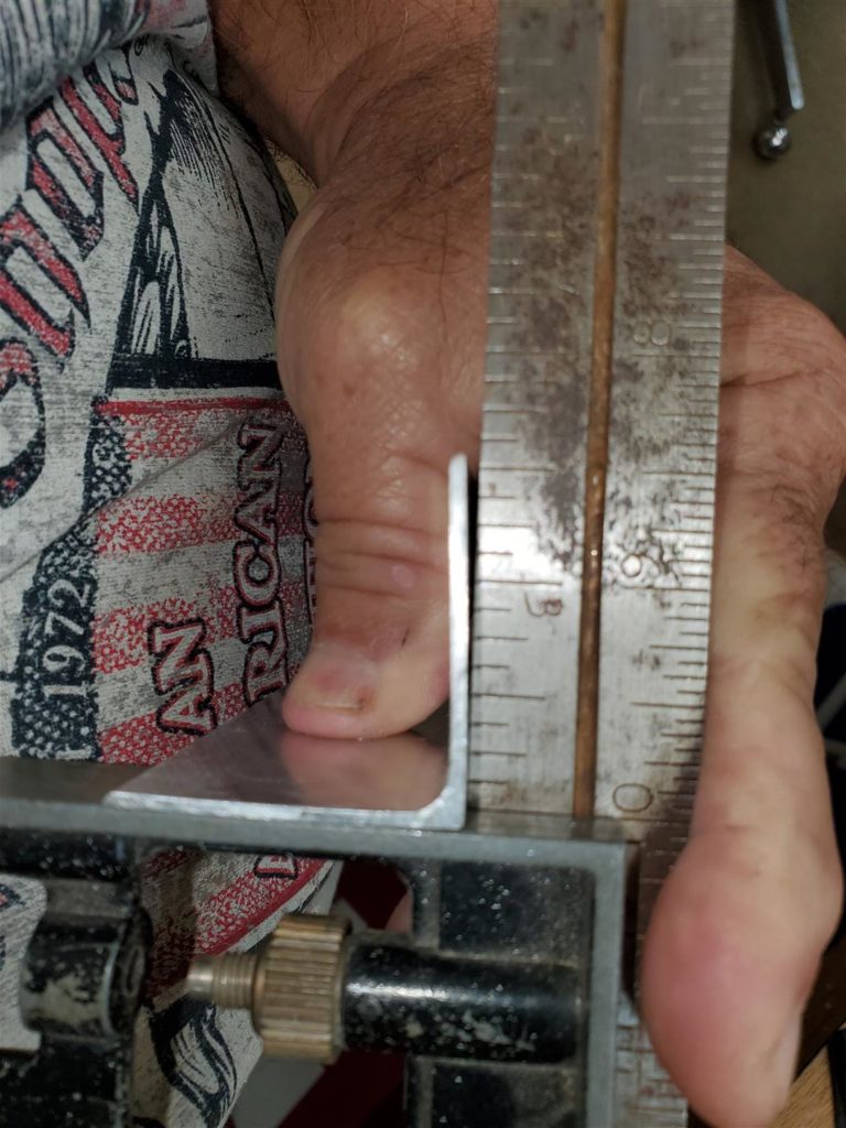
I noticed the angle was not a true 90 degree angle when I test fitted these.
So, I had to bend them into shape to ensure a proper fit.
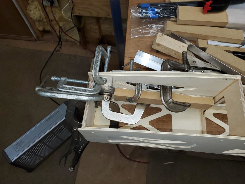
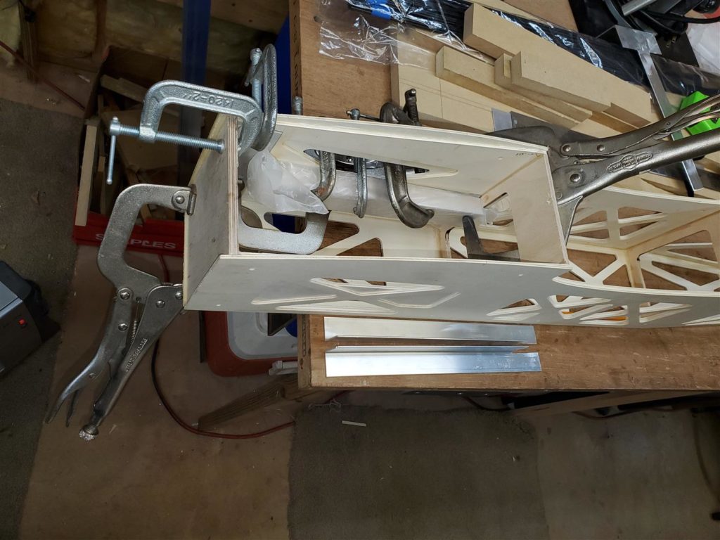
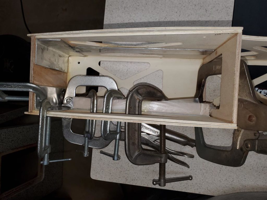
Then glue the supports in with 30 minute epoxy. Use LOTS of clamps and a block where needed.
They must be firmly attached to the wood.
Wrap the block in waxed paper to keep it from gluing to the support.
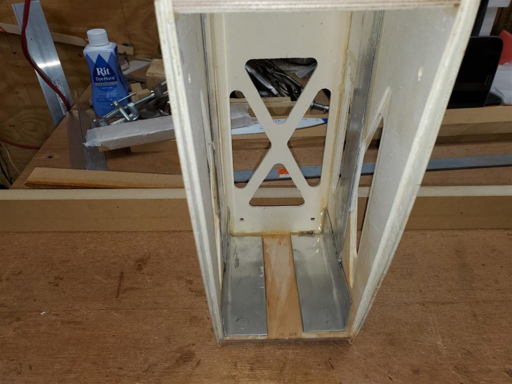
The landing gear supports will be glued in later. Fuel tank and ignition supports will be installed first. The gear support angles are cut to fit from the firewall to the first former. They will need some trimming to allow them to fit at the firewall end. The bottom edges may also be trimmed later to make more hand room for an access door.
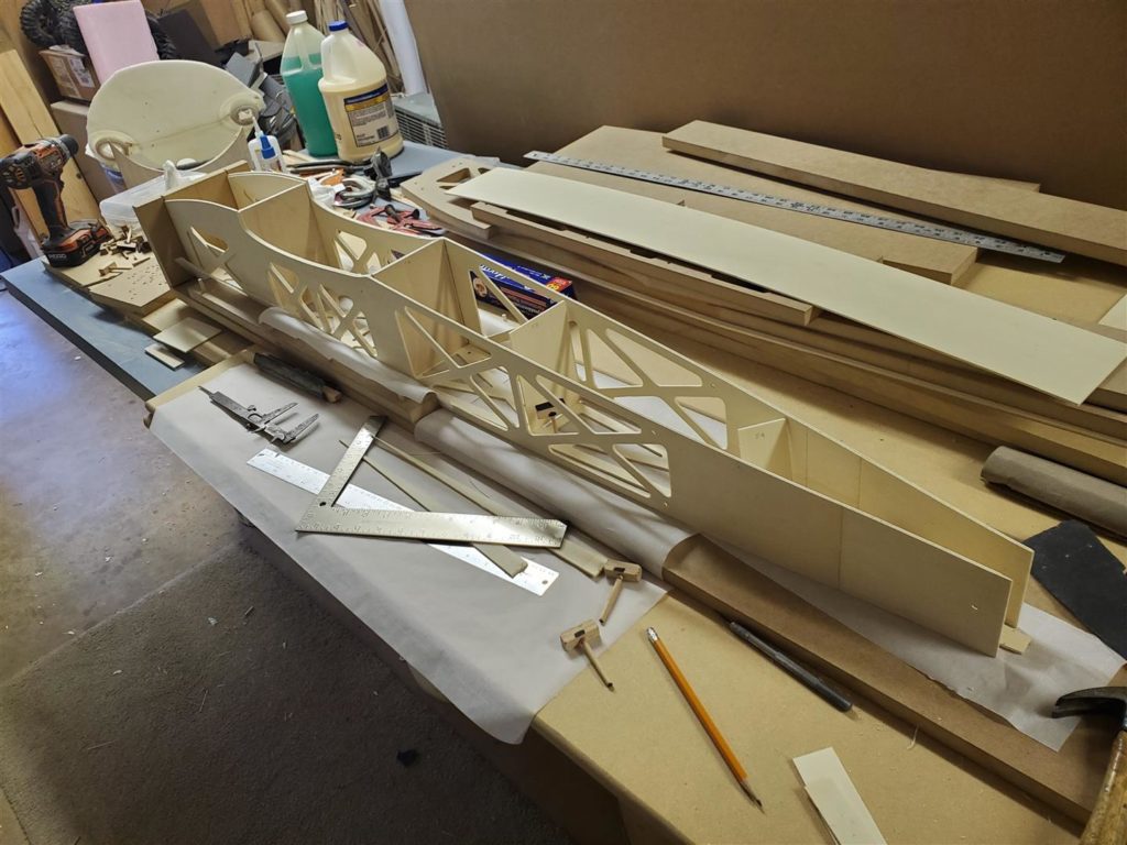
Here are some pictures of the fuselage after reinforcement and final gluing.
Now the fuselage is ready to be fitted with all the rigging and parts to make it into an airplane.
Wing Construction
Wings for the BipeGnat will be made of foam, epoxy, fiberglass and balsa. The process used is a common process except for the order of materials used during lamination.
The first step in wing construction is to cut the wing cores. A hotwire is used to cut the wing cores from larger blocks of foam.
Next epoxy is used to laminate the foam cores with fiberglass and balsa. The laminated wing cores are pressed together while the epoxy sets using a vacuum bag and vacuum press.
Most who vacuum bag foam core wings usually laminate with the wood, usually 1/8″ balsa or thin plywood on the inside layer and the fiberglass on the outside layer. While this is also very strong and done in much the same way, having the wood on the outside makes final shaping and using coverings very easy.
Mike Waters discovered that there is strength in laminating a sheet of 3/4 ounce fiberglass and a sheet of 1/16″ thick balsa onto the top and bottom of the foam core. Epoxy is used sparingly to adhere sheets of fiberglass and sheets of balsa to the foam. He then vacuum bags the wing while the epoxy cures. This makes the foam, fiberglass and balsa become one unit and very strong. The end result is a very light and durable wing.
Many are skeptical at first like I was. They may think that 1/16″ balsa will not provide much strength. But I have seen its strength first hand. I also tried to break a piece with my hands but could not break it without a tremendous amount of force.
Finally, the wing edges are surrounded with balsa and lightening holes are cut in the wing with a router to reduce weight.
Note: If you do not have the tools needed for this process they can be made in most home shops. See the Tools section of this website.
Let’s get busy building some wings.
Foam Cutting
The wing cores were cut from blocks of 1# density foam. I cut a 6″ x 24″ x 36″ block of foam into 3″ x 12″ x 36″ blocks. See the Sources page of this site for Foam Suppliers.
The wing cores were cut with my hotwire cutter from four of those blocks. See Tools, Hotwire Cutter for further details on how to cut the foam.
Wing Sheeting
I have watched Mike’s video on sheeting foam core wings several times.
I applied it to my first vacuum bagging attempt. I highly recommend watching the video before reading the rest of this post.
I took notes to help me remember the tools and materials needed and the steps in the process. Mike offered a wealth of data in the video. These are my notes albeit edited for posting.
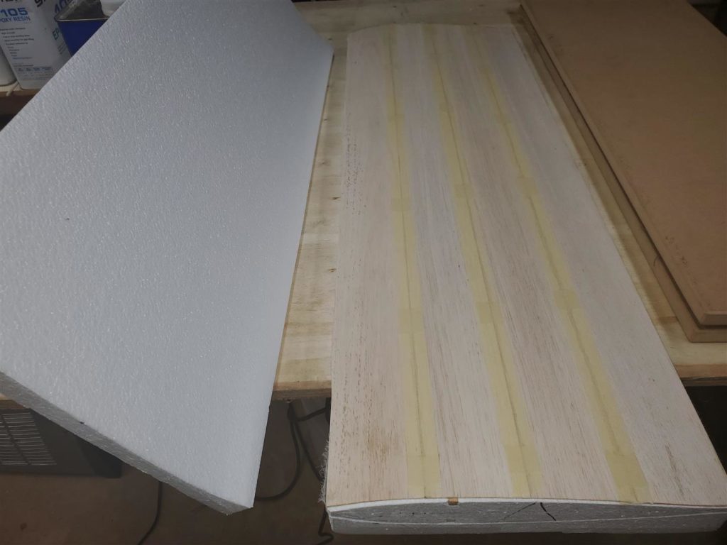
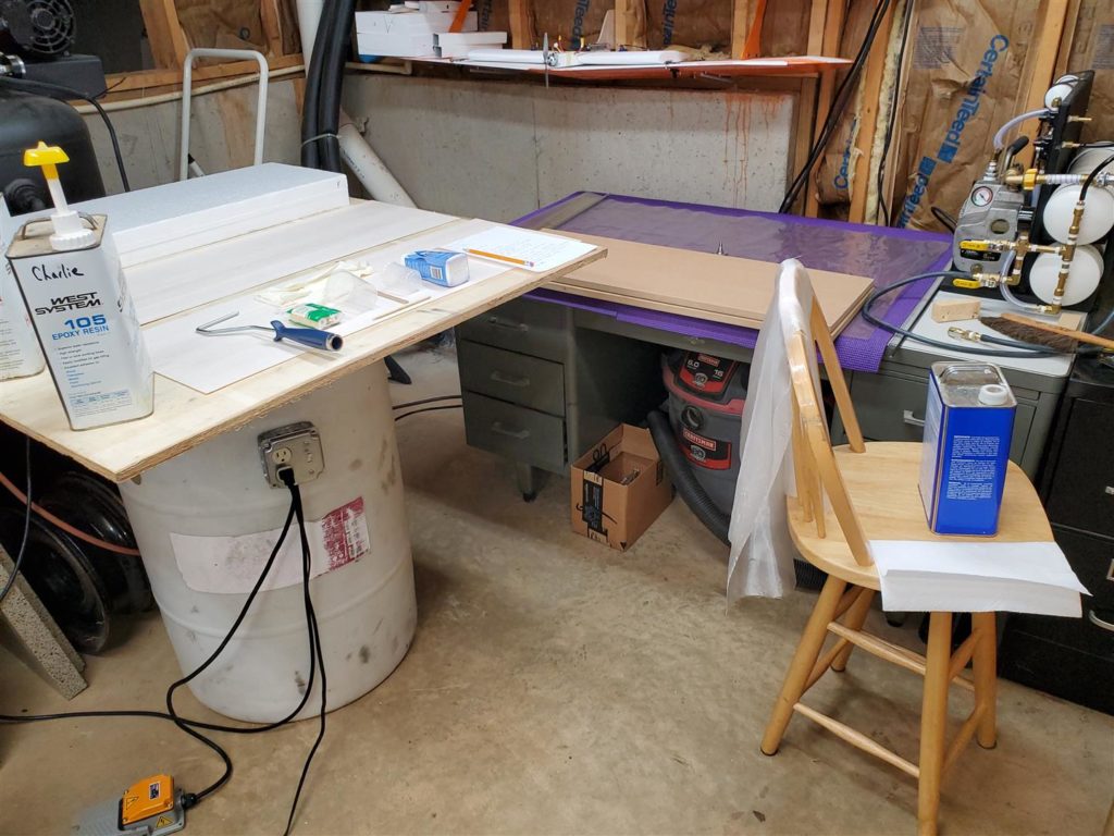
The work table should be large enough to lay the foam block and both balsa sheets side by side. Mine is a piece of 1/2″ x 43″ x 43″ cheap plywood laying on my router table. The 1/16″ x 3″ x 36″ sheets of balsa are taped tightly together at each edge. Then the whole sheet is trimmed to fit the wing core. These balsa sheets are already taped together on the opposite side.
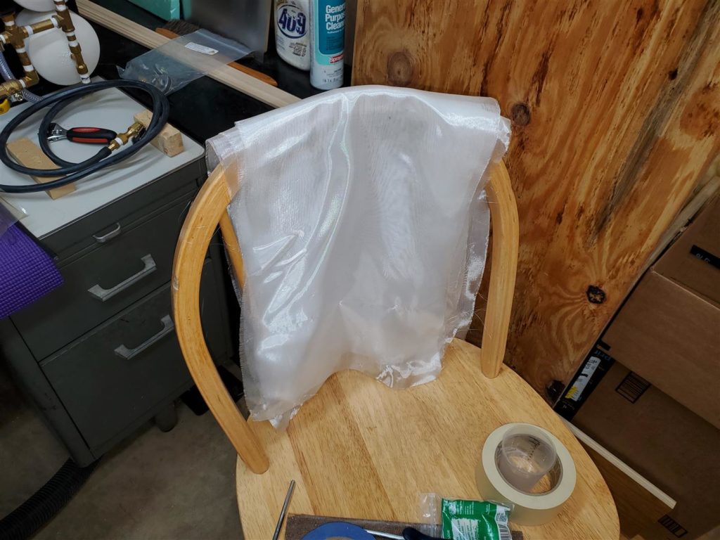
Next cut the 3/4 ounce fiberglass cloth to size. Try not to handle it any more than absolutely necessary or it will lose its shape. Drape it over a chair or stand near the work surface.
Now is the most challenging part. Getting everything together so you can get the laminations all glued in a reasonable time. This is a list of things Mike suggested or used in his video:
Foam cores in their shucks
1/16″ x 3″ x 36″ balsa sheets taped together
3/4 ounce fiberglass sheets
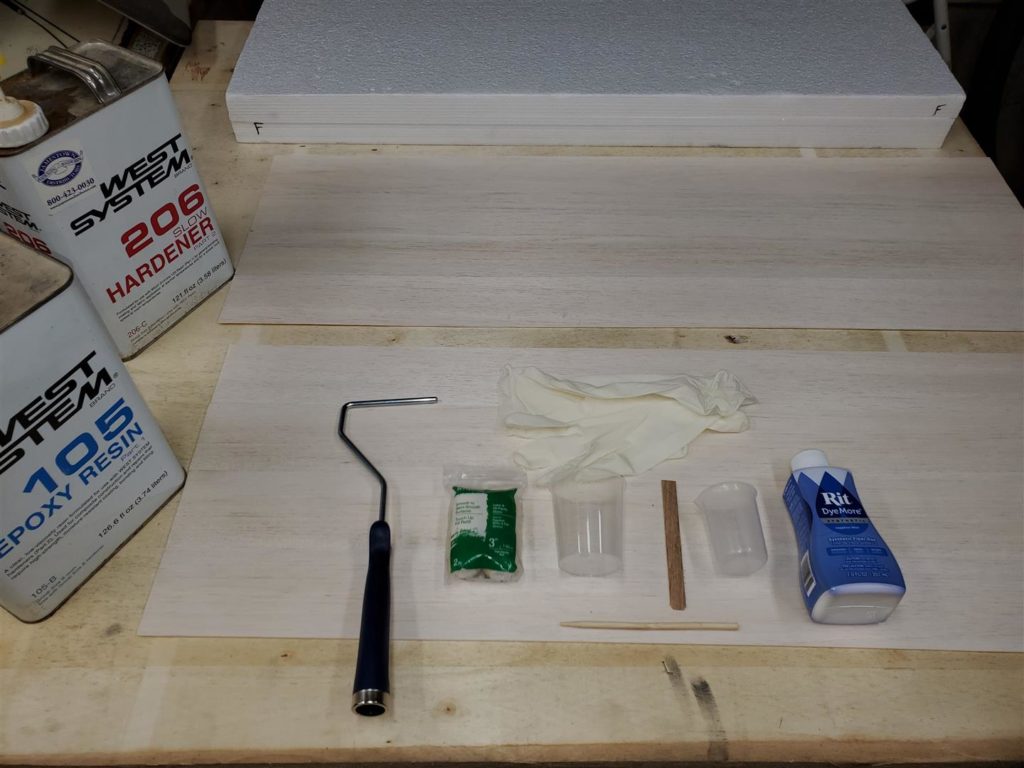
West Systems 105 Epoxy and 206 Hardener
Rit Dye
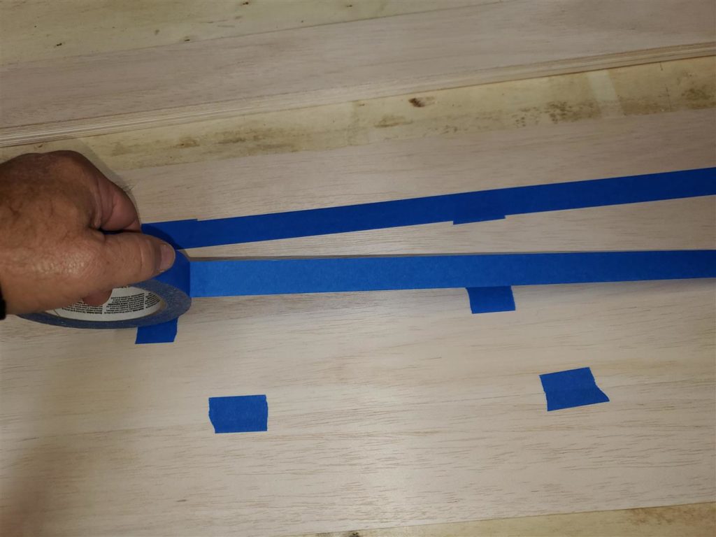
3M 1 Blue 2090-24EVP, .94 in. x 60 yd. Scotch Painters Tape
4 oz. Graduated Transparent Polypropylene Plastic Cups
Stirring sticks
Paper towels
Denatured Alcohol in a spray bottle
Latex gloves
3″ paint roller and handle
36 grit sanding block
Exacto knife
Vacuum bag and bag seals
Burlap
3/4″ MDF platens
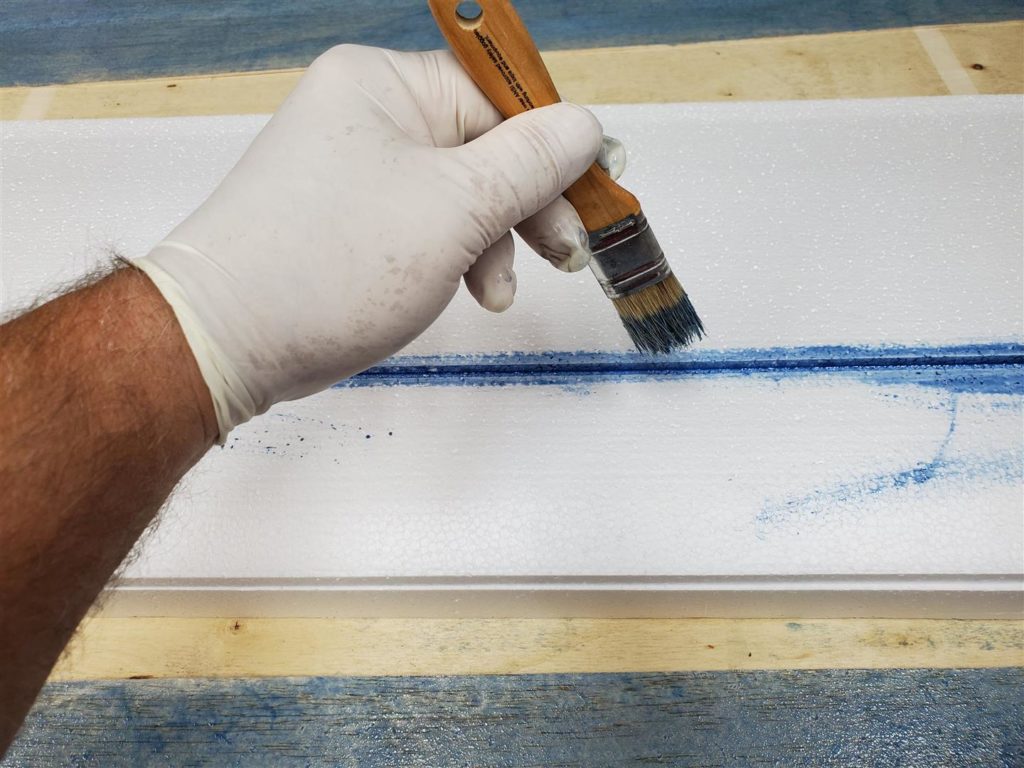
The wing cores I am making have a 1/4″ square balsa spar. So I also needed a small paint brush to put epoxy into the groove in the foam. Mike later told me that this step really isn’t needed since the vacuum will pull the epoxy all around the spar. He simply paints a very thin layer of epoxy on the wood spar and lays it in the dry spar grove. He uses spars on his little flying wing pylon racers. Inspections of broken wings over the years revealed that very little epoxy is needed on this spar to achieve incredible bonding with the surrounding foam.
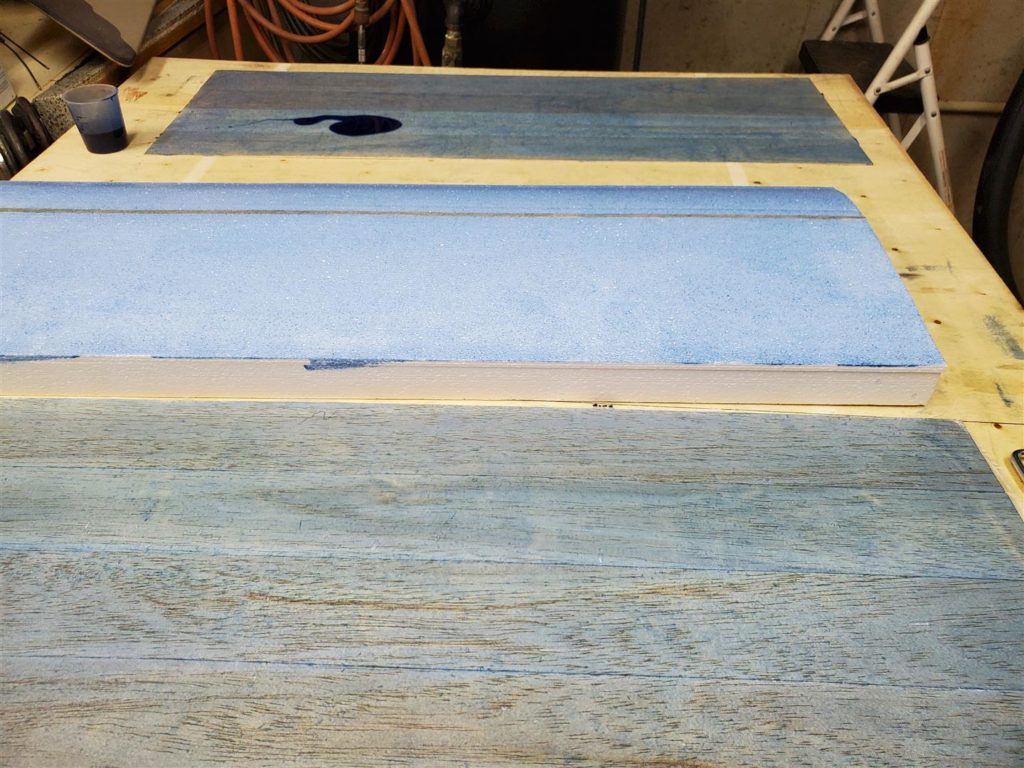
Mike choked when he saw this photo. I may have used a bit too much epoxy. Also, don’t too much Rit Dye. The color may bleed through the balsa more than you like.
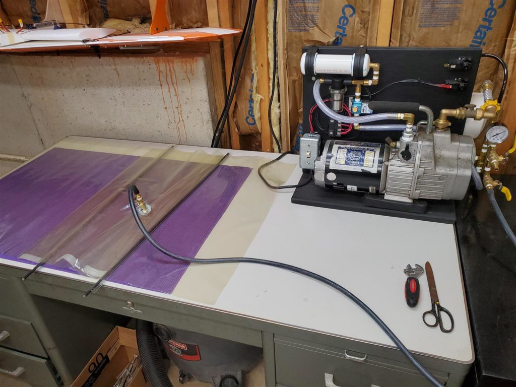
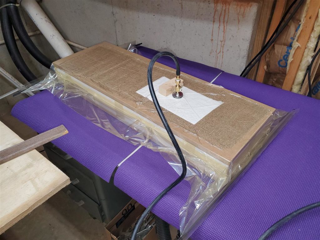
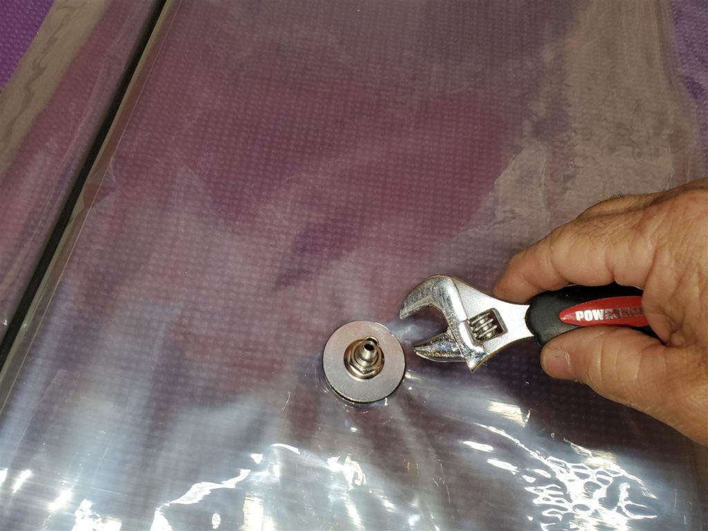
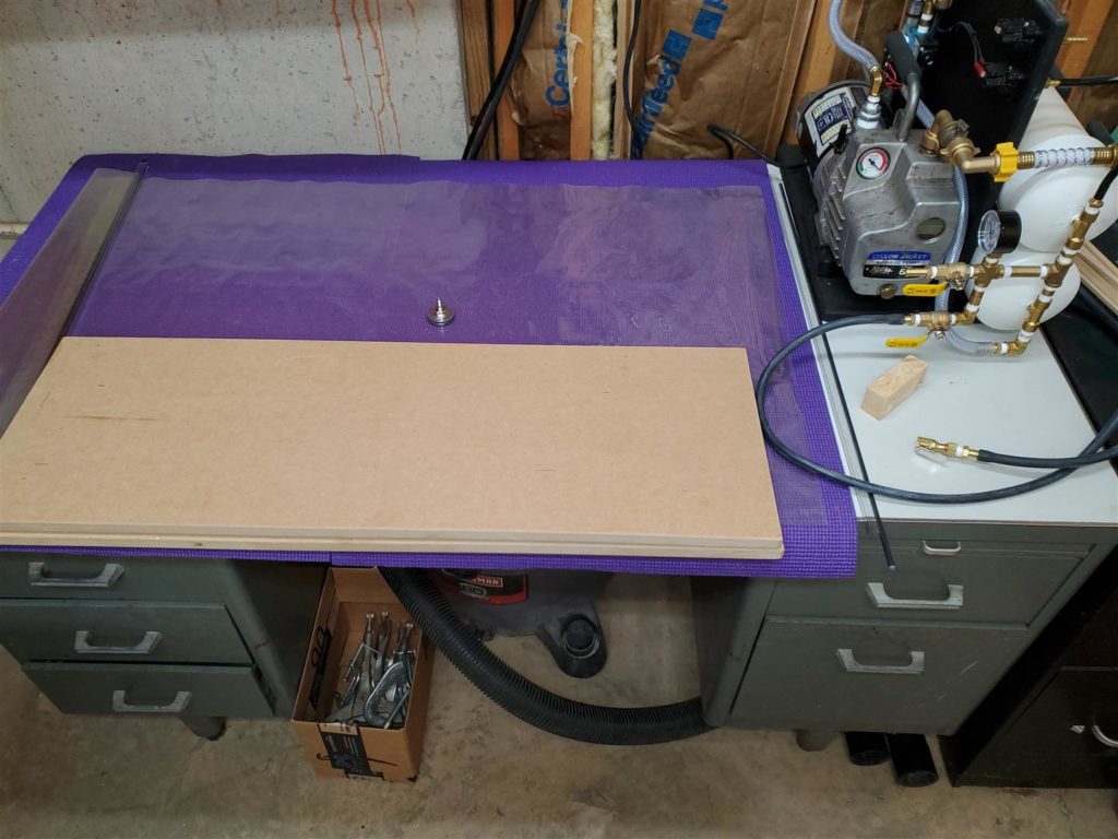
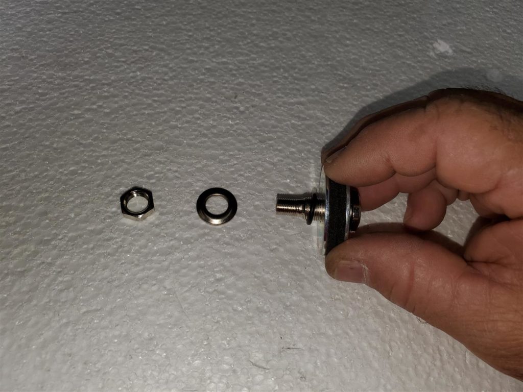
I started with some new bagging material. It is a 27″ wide vinyl tube that you can buy by the foot from https://www.cstsales.com/. I cut this one to about 50″ long. The valve was purchased when I got the parts for the vacuum press from https://www.veneersupplies.com/. I pressed a hole with a hole punch to make a nice smooth round hole for the stem. Be sure to use the rubber washers and O-ring to seal the stem.
See the resource page for links to these and other suppliers.
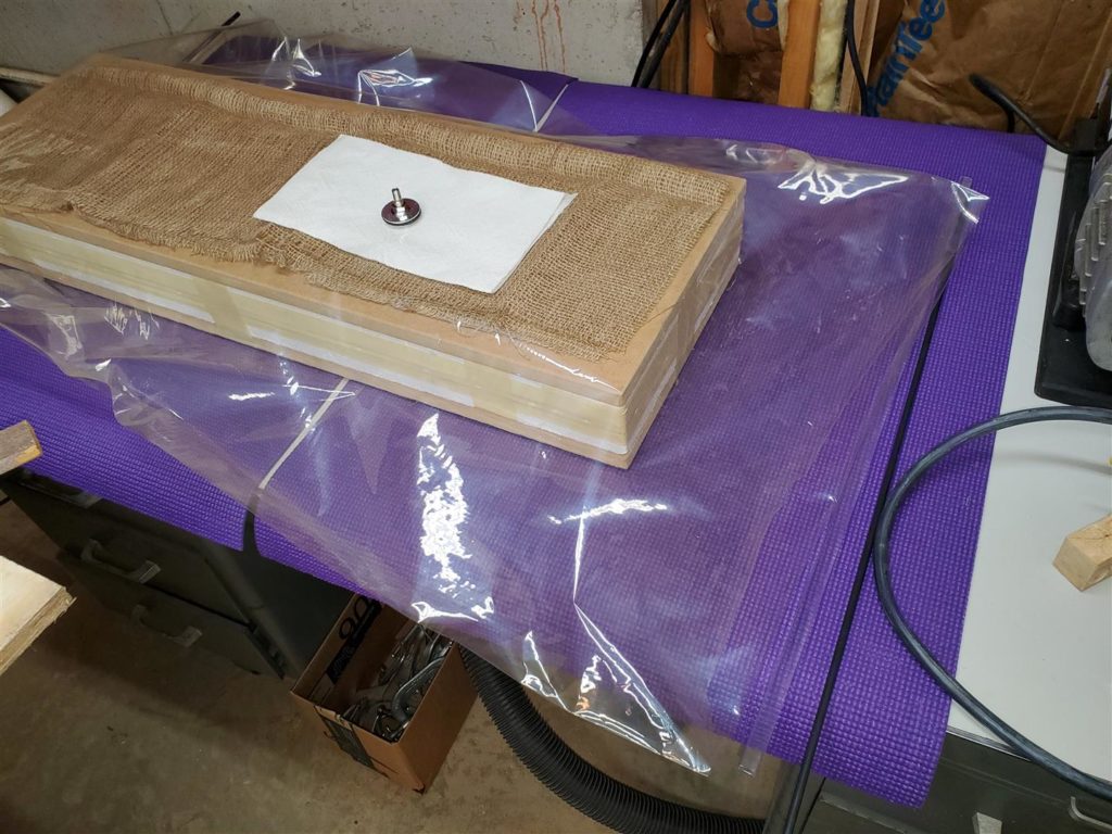
Place the stem where it will be on a flat area of the platen when in use. Mike likes to place a paper towel under the stem to act as a filter. The system has a filter in line but stopping styrognats here is very easy.
I also have a purple Yoga mat that I lay over the table for the vacuum bag to lay on. Mike uses foam blocks. Protect your vacuum bag! Have it ready before proceeding.
1
The rest is “Super Easy” if you watched the video.
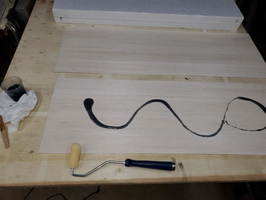
Mix some epoxy per the label directions. We use West Systems Epoxy and 206 hardener to allow about 30 minutes of working time. I made 3 oz. of epoxy and had to mix a little more at the end. Next time I plan to mix close to 4 oz. Add some dye to the epoxy. It is very difficult to see the epoxy coat if you do not use the dye. Complete coverage is necessary to achieve a strong bond.
Spread the epoxy over the two balsa sheets fairly quickly to keep the heat down. If left in the mixing cup, it will heat rapidly and can even melt the cup. (Ask me how I know.) Tall cups are problematic for mixing epoxy. Using a shorter and wider cup will keep the pool of epoxy shallow and slow the exothermic reaction. Roll the epoxy out thinly but with even coverage on both balsa sheets.
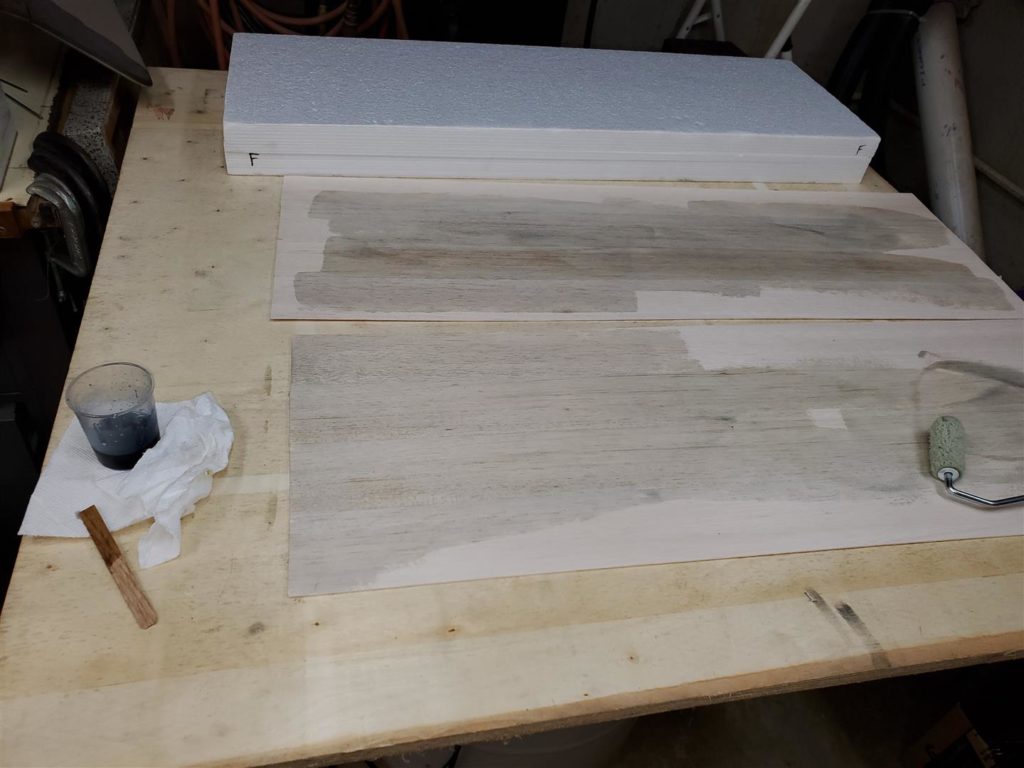
Roll epoxy onto the first side of the foam core. Keep this very thin. All it needs is to be wetted with epoxy to ensure a good bond. I need a dropper so I can add more dye. It did not come out dark enough once it was spread out.
Now carefully lay the fiberglass sheets onto the balsa sheets. Try to avoid wrinkles as you lay it down. It will not move very easily after it gets epoxy on it. Roll the fiberglass with the damp roller to remove the air pockets.
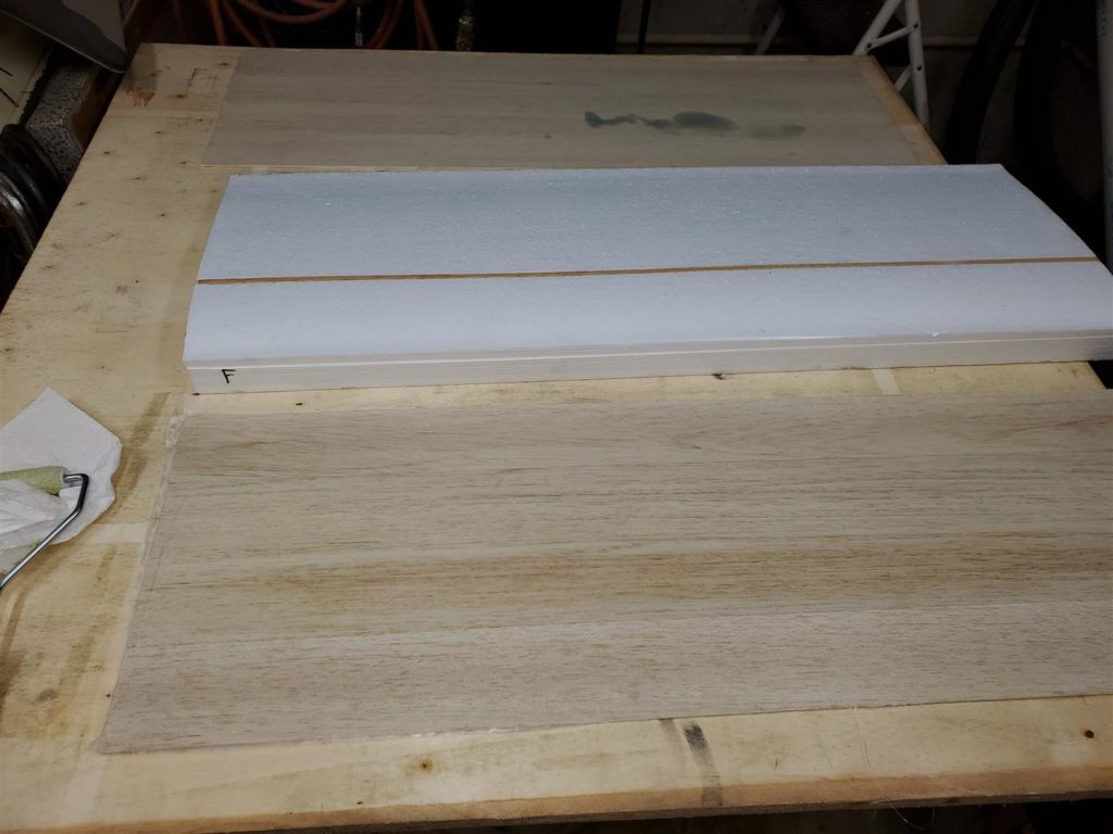
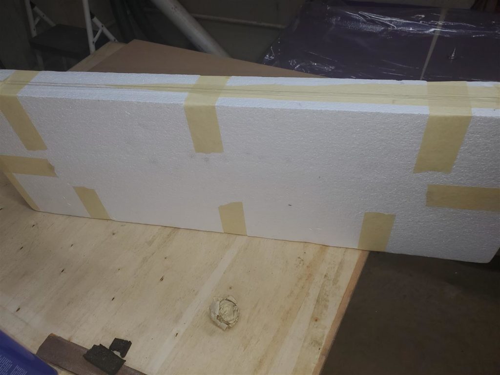
Lay the balsa/fiberglass laminate onto the wing core. Carefully align the ends and the trailing edge of the laminate sheet and the foam edges. The trailing edge of the foam block must be made even and square. This “perfectly flat and aligned” side of the entire assembly will be placed against the table saw fence later to trim everything up. Place the shuck over the first side while keeping everything aligned on the trailing edge. Turn the block over and do the same to the other side.
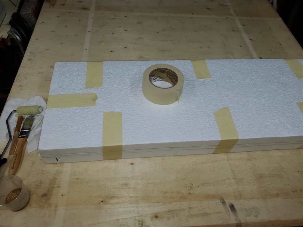
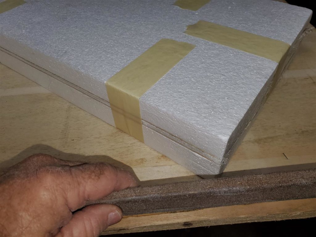
Hold everything in alignment tightly and put masking tape on each end as clamps and then along the sides.
Sand the end corners to make sure there are not sharp edges of balsa to puncture the bag.
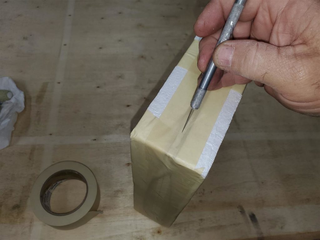
Now cover the entire mid-section of the foam block to be sure all fiberglass is kept away from the vacuum bag. The hairs become like needles as the epoxy cures. The tape also seals the epoxy in under the foam so it does not adhere to the vacuum bag. Use the Exacto knife to poke holes in the tape along the sides of the foam. This will let air escape.
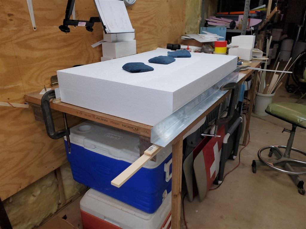
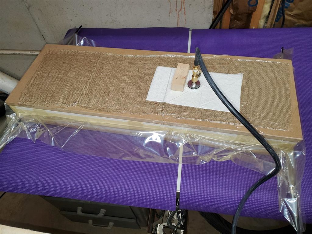
Tape the block onto a platen at each end and middle of the sides to keep the block from moving while placing it in the vacuum bag. Slide it into the bag. Slide the top platen over the foam block. Add some burlap on top of the platen and a paper towel at the air outlet to filter the air and keep trash out of the vacuum system.
Seal the end of the bag and connect to the vacuum system.
Turn on the vacuum pump. Watch and be sure the vacuum bag does not get pinched while the air is removed and that there are no wrinkles in the bag material on top of the work piece.
9″Hg is adequate. If the system cycles up to 9″Hg and down to 8″Hg it will work well. The system should not cycle often. It should be able to hold the vacuum for around 10 to 15 minutes unless there is a leak. Mine is cycling at about 2.5 minutes. So I need to find the leak. It is working but the pump has to start too many times with the leak.
Leave the vacuum system on for about 3 hours or longer. The epoxy has to set before the vacuum is removed.
I left it on for almost 4 hours to be sure the epoxy went off. Cooler temperatures will require longer set times.
It took a few minutes to remove the tape but the result looks good.
Notice the yellow tape on the balsa seams. Mike pointed my error. That stuff is hard to remove without damage to the balsa. USE blue painters tape when taping the basla together!
The removal of the tape took a while but it did come off. The pressure inside the bag pressed it on really firm. Again, use the blue tape on the balsa!
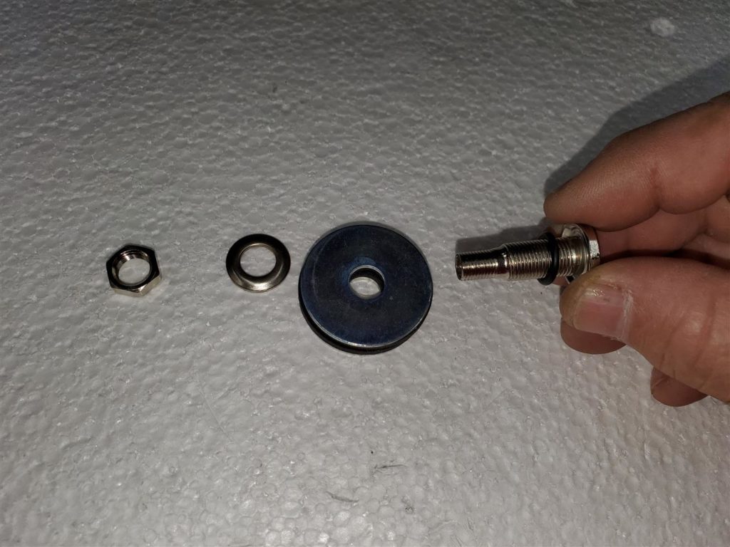
Note: I found the vacuum leak after making the first wing. The old style valve I purchased for the bag came with an O-ring. I put it all together the way it was stacked when I got it. Turns out the threads will let air in if the O-ring is not in the correct position.
This is the correct position. The O-ring seals the stem against the metal washer on the inside of the bag. That keeps the threads from leaking.
I tested the empty bag. Now the vacuum press cycles once in 59 minutes for a couple of seconds! I am glad it is now working correctly.
Success! What a relief. I think the next ones will be better now that I have some firsthand experience.
We will get back to the wings later.
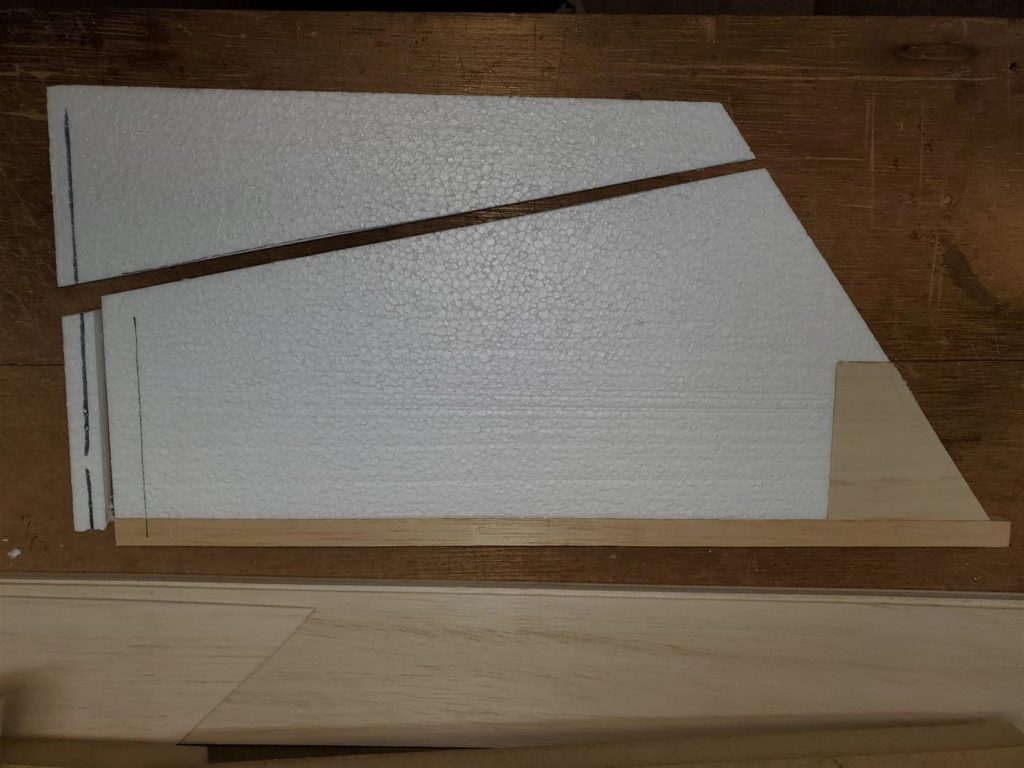
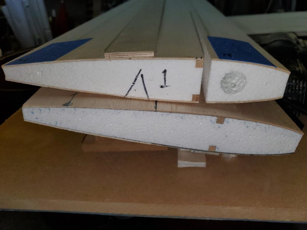
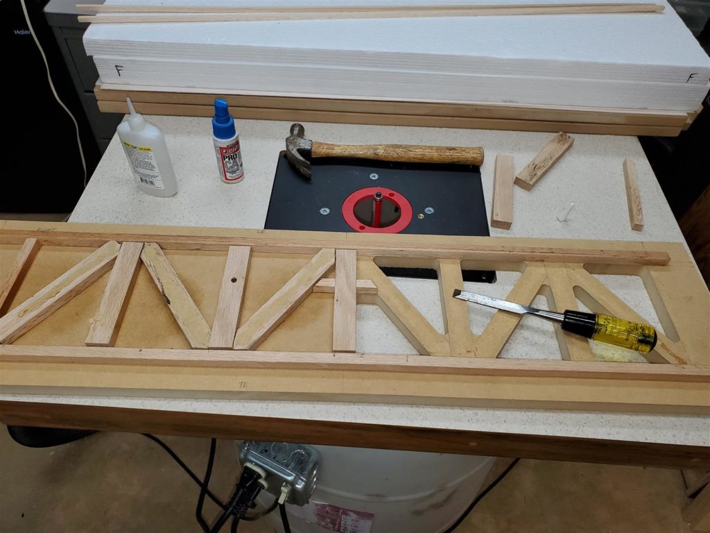
Control Surfaces
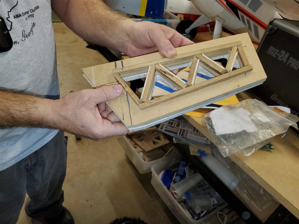
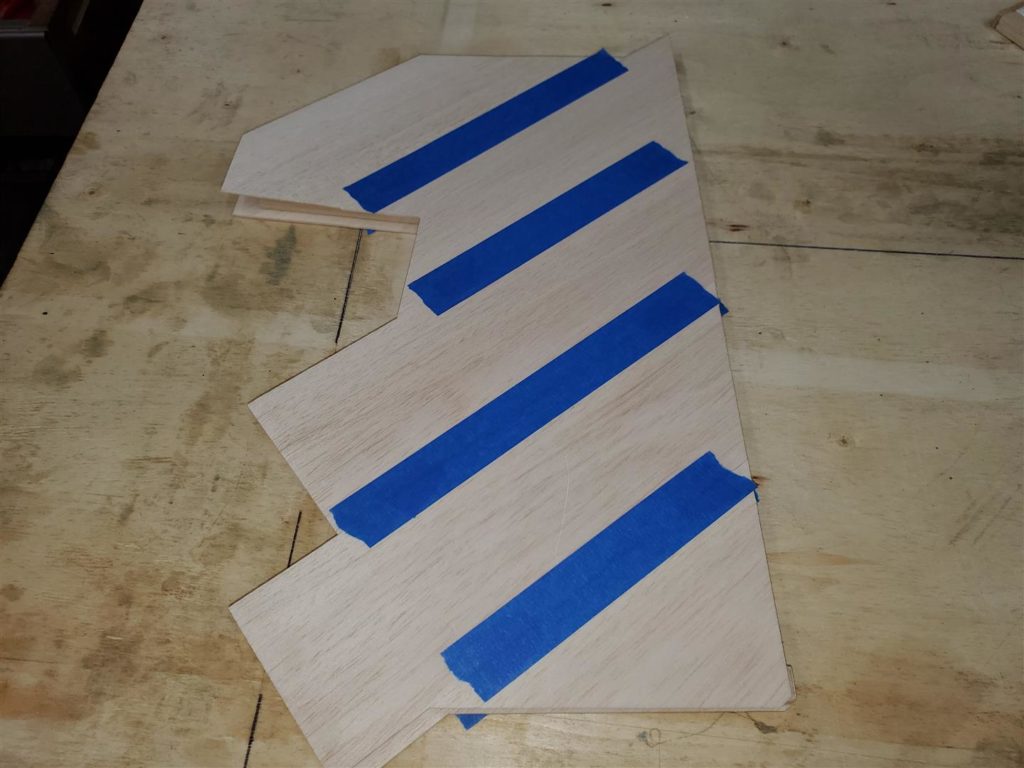
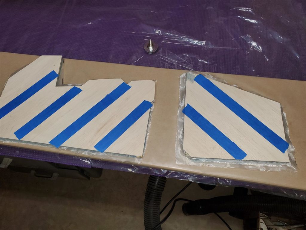
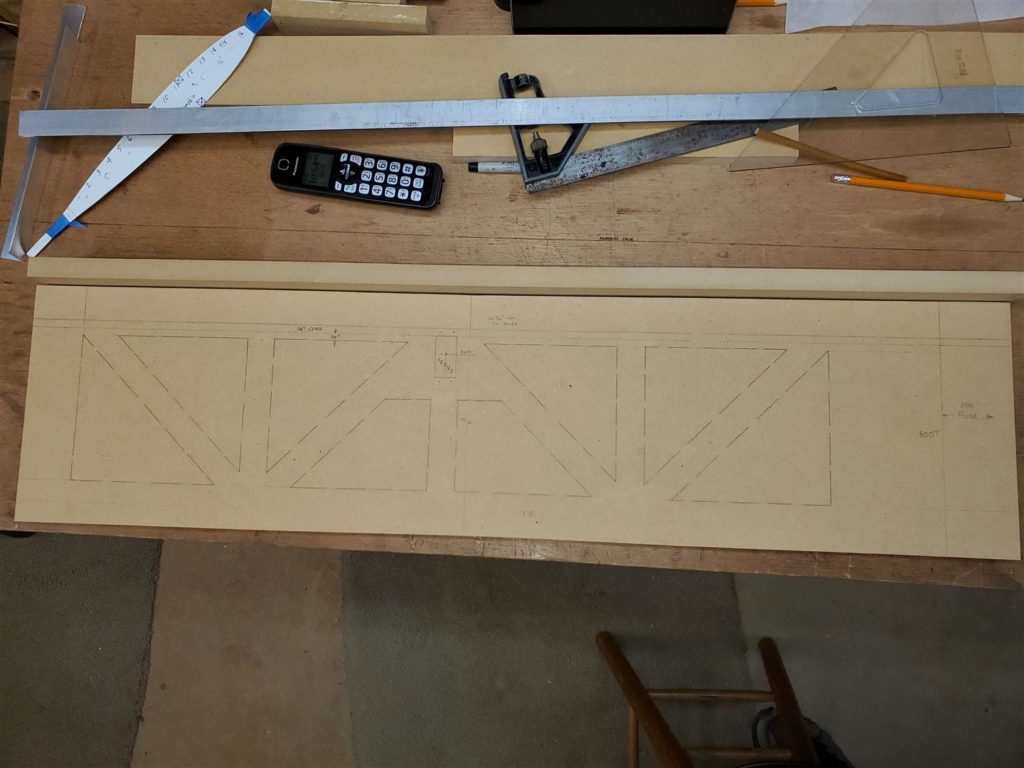
The control surfaces are constructed of foam core laminated sheets with balsa around the edges. They are 1/2″ thick flat surfaces on the BipeGnat. The foam core is 3/8″ thick with some pieces of 3/8″ thick balsa in strategic locations. The laminate is the same 1/16″ thick balsa with 3/4 ounce fiberglass cloth. Templates are used to trim them into shape and lighten them.
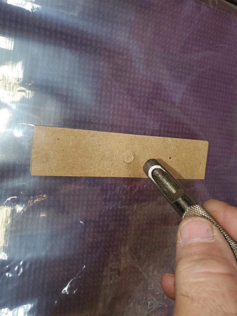
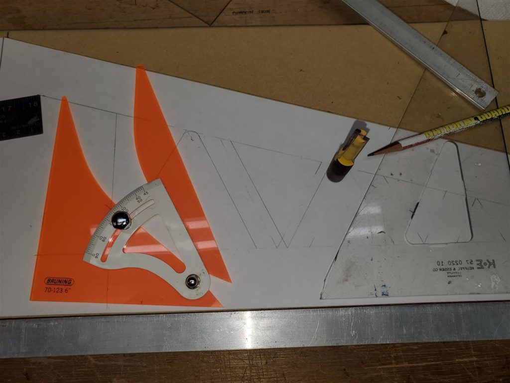
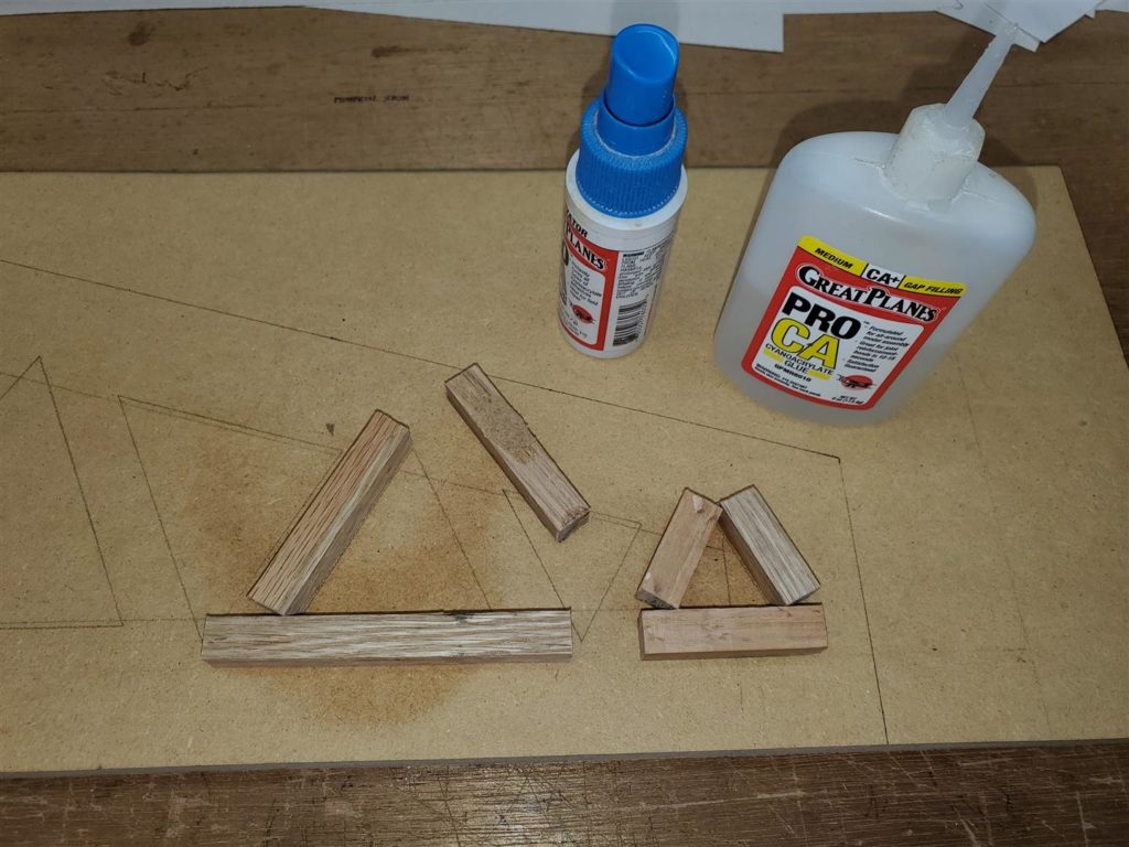
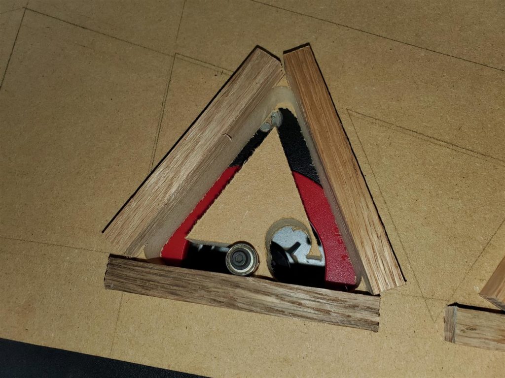
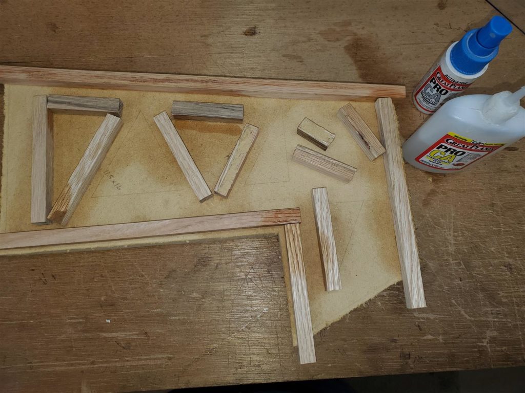
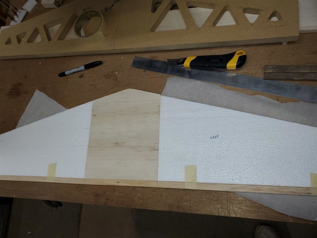
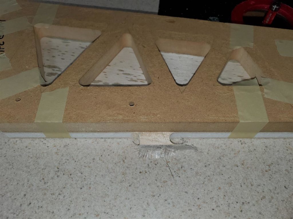
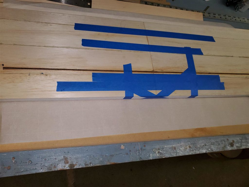
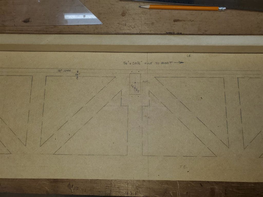
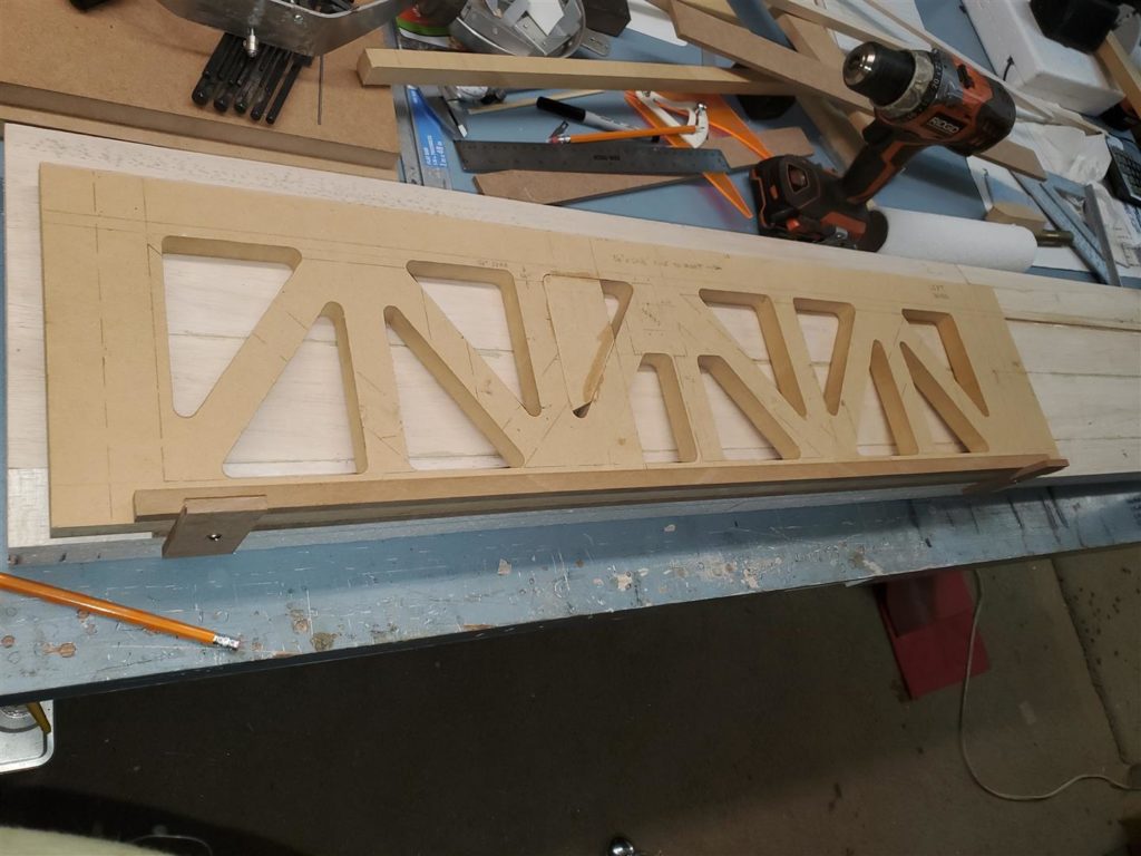
The first step is to lay out the part shapes and where the lightening holes will be made. Notice the rounded corners. I used a 1/2″ router bit end to show where the edge of the flush trim bit will cut to. The triangles extend beyond that point but the bit will stop at the place shown on the drawing.
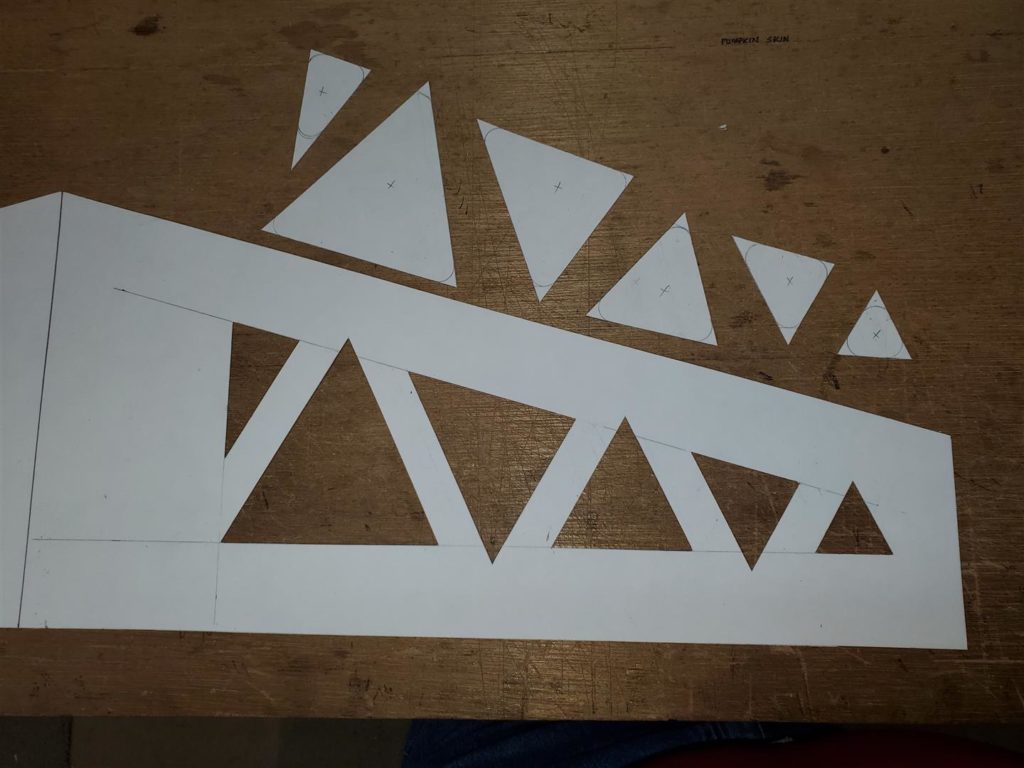
Cut out the shapes on the poster board.
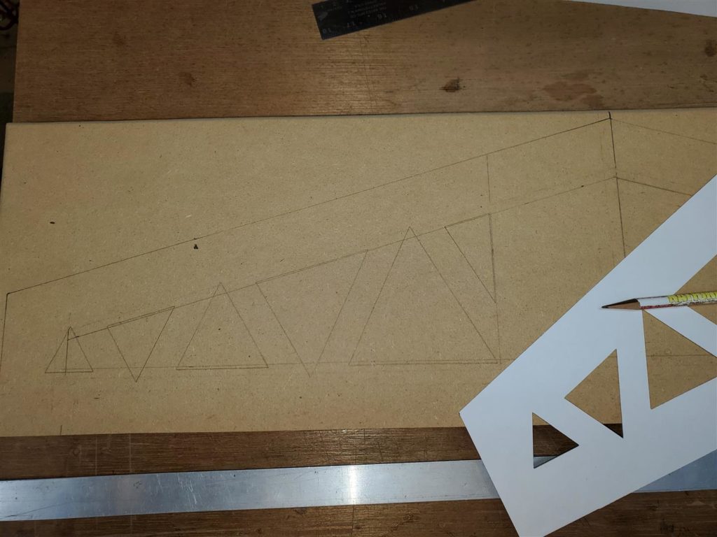
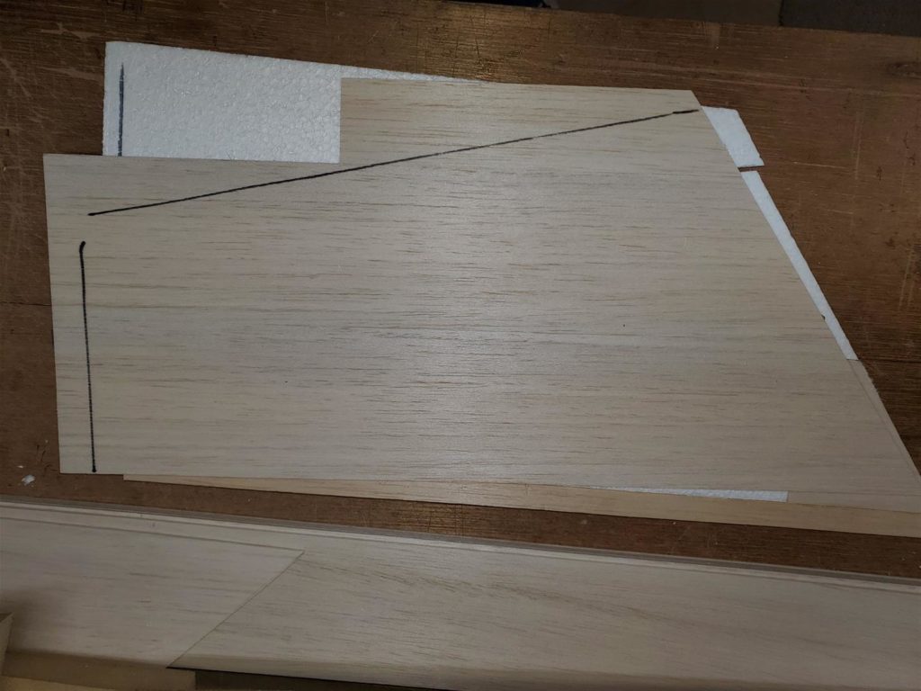
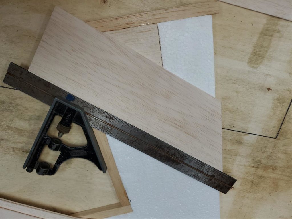
Trace the paper template onto some MDF.
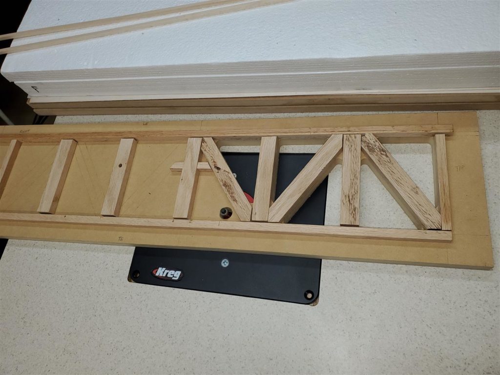
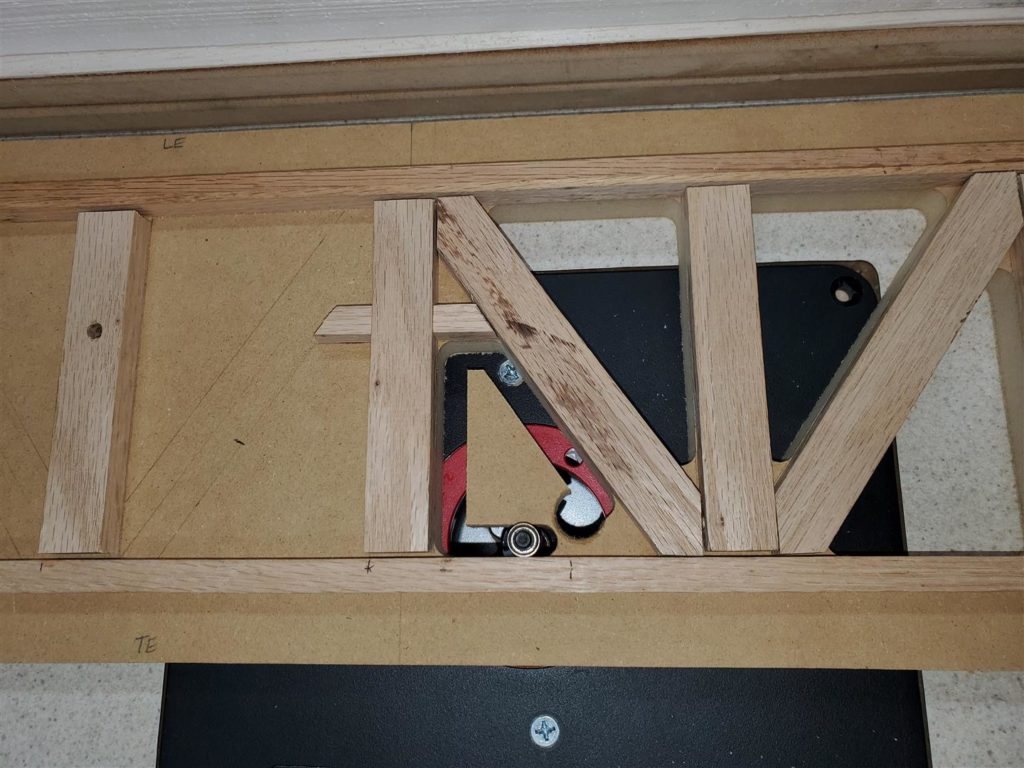
7/16″ square guide strips are glued onto the MDF to guide the router bit. Go light on the glue. The strips will be removed after the holes are cut.
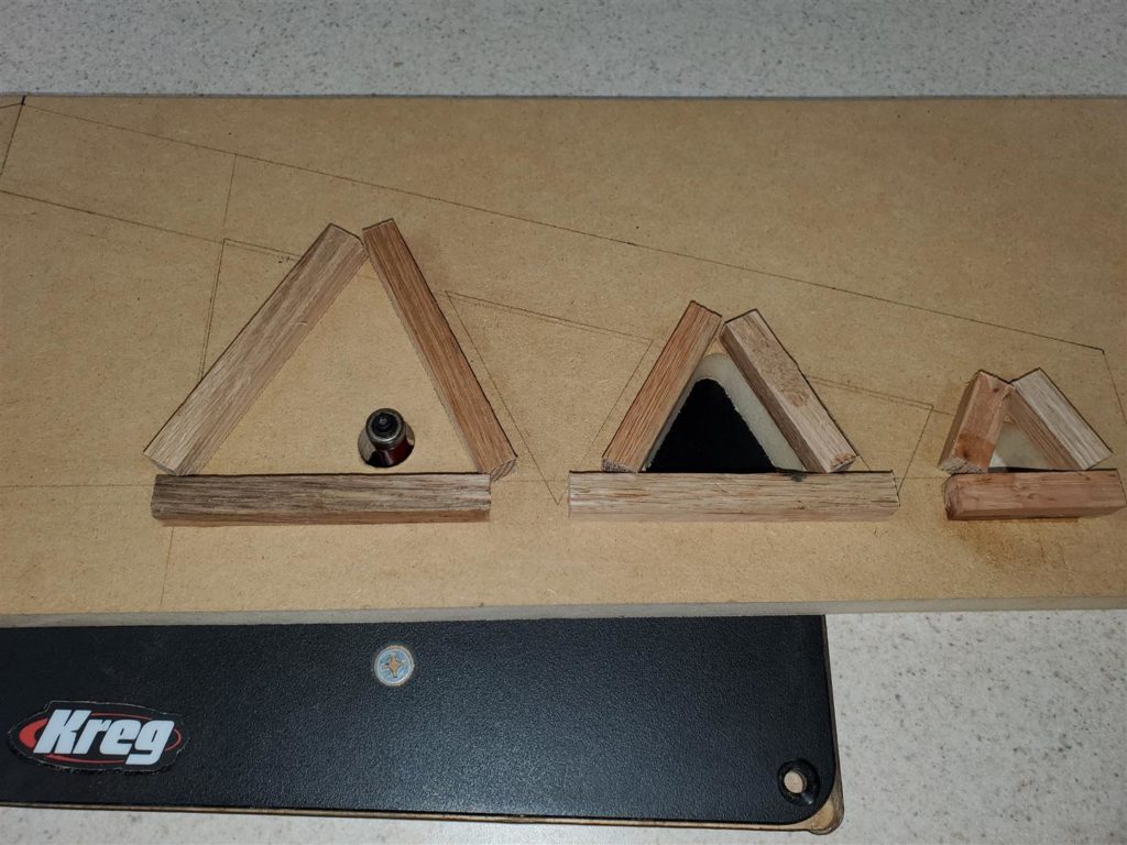
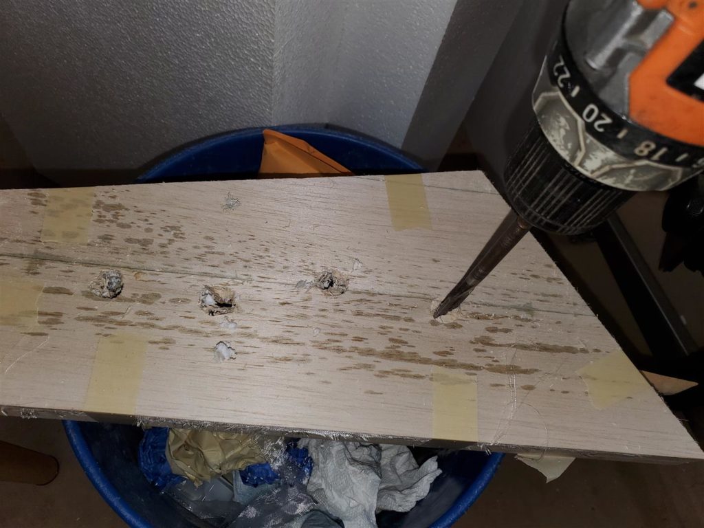
Drill holes and cut out the waste with a 1/2″ flush trim router bit.
Be careful to stop before the waste piece comes loose. It can hurt you!
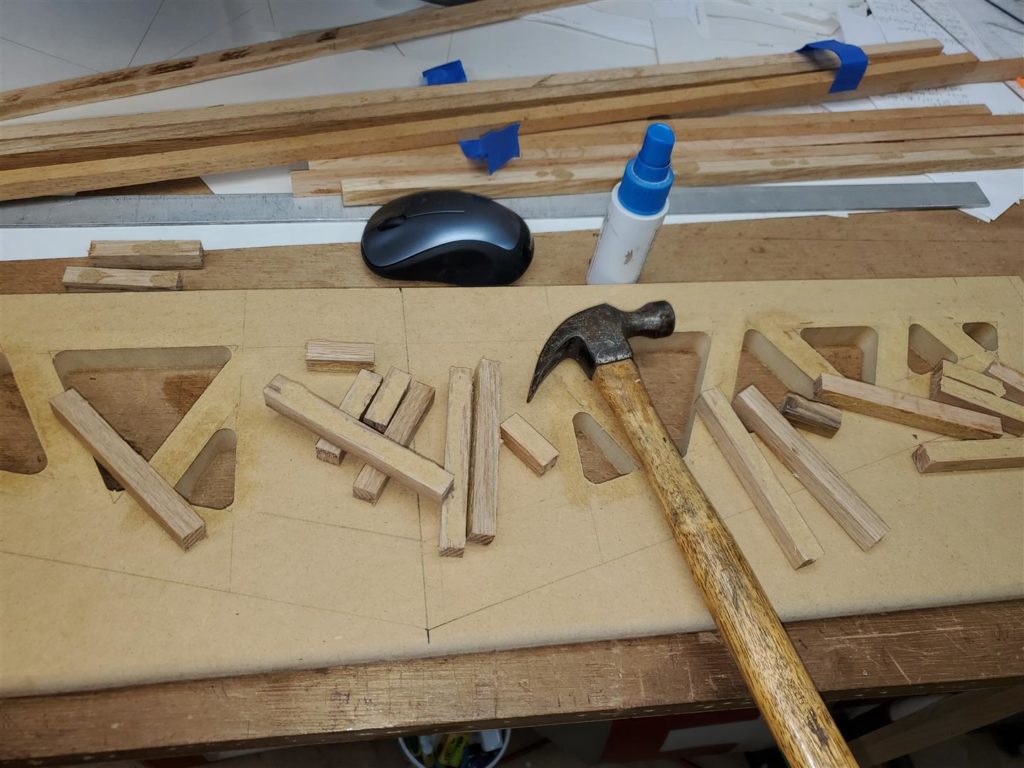
Break the guide strips off with a small hammer and chisel.
The edges can be made flush the same way. Just be sure to use a very straight guide strip.
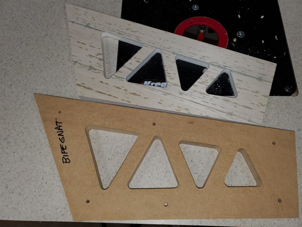
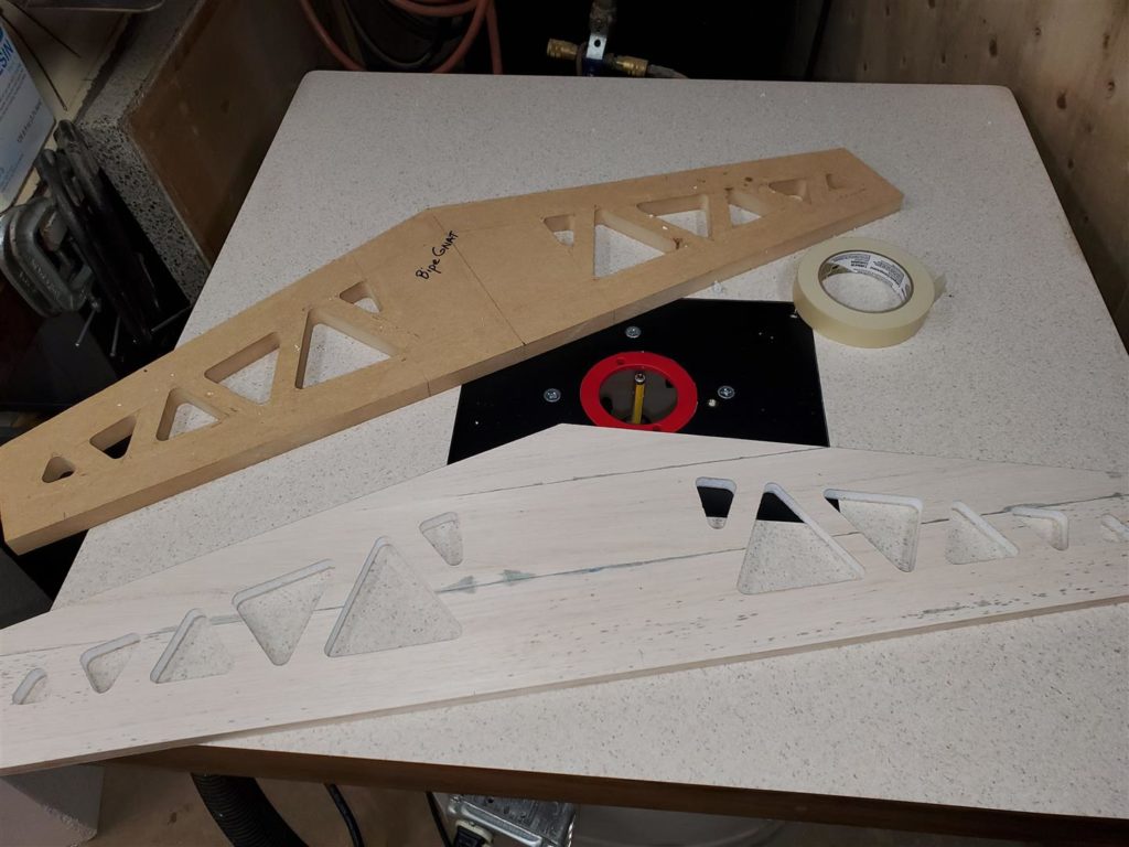
The horizontal stabilizer template is finished.
This is the rudder template under construction.
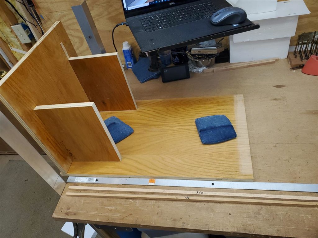
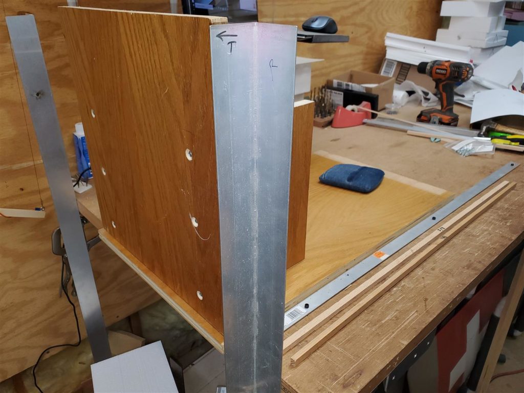
A Next some 3/8″ thick foam sheets are needed to make the parts. I built a sled that can be positioned against a 1/8″ aluminum strip and slid to make the thickness of sheet I want to cut. The aluminum strip is squared to the front of the sled and aluminum angles to make square foam cuts.
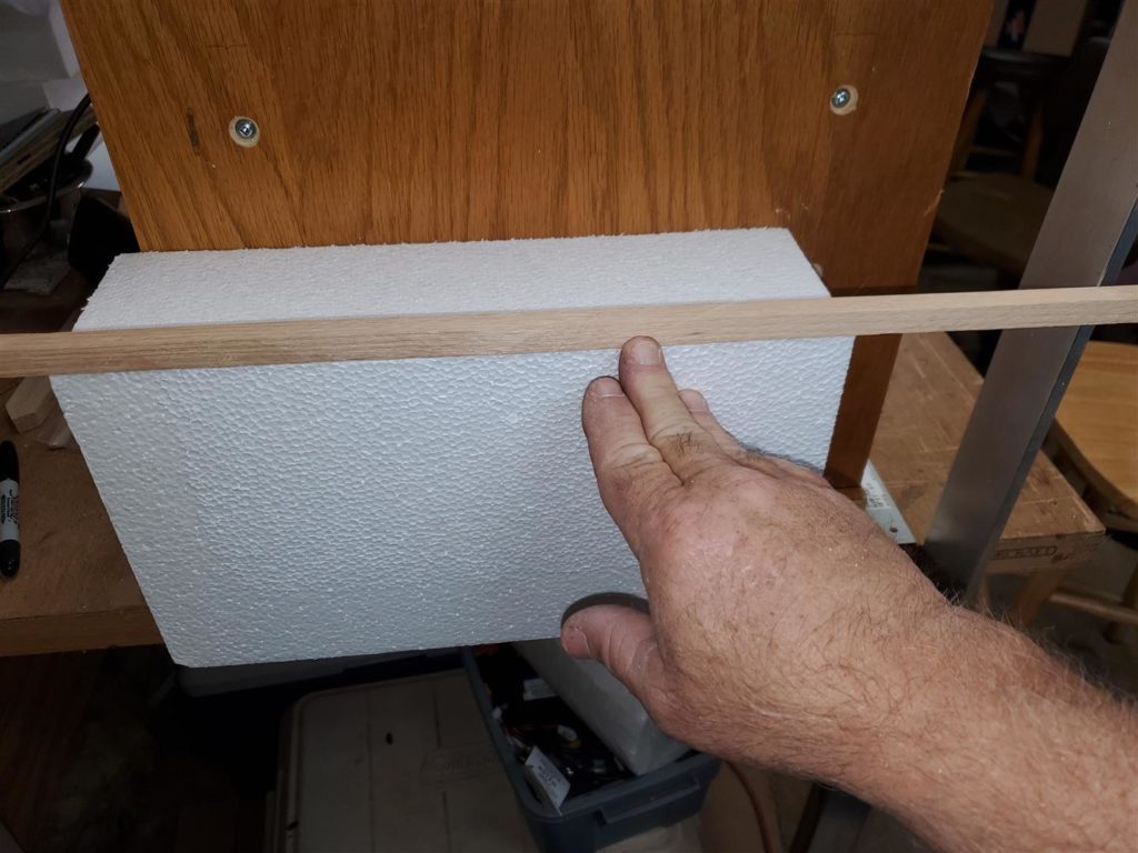
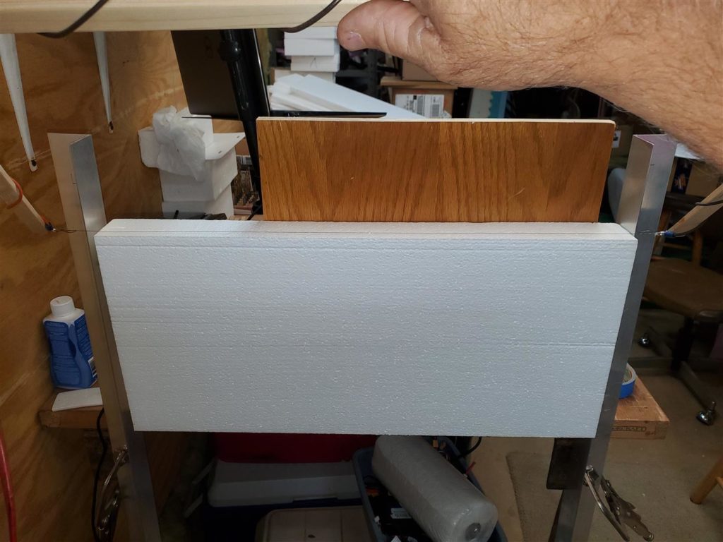
The block of foam is placed onto the small lip at the bottom of the sled and held against the flat front of the sled.
I use a strip of wood to set the thickness the sheets will be cut.
The hotwire is used against the aluminum angle guides to cut the slice of foam from the block. I use my other hand to hold the block to the sled when I am not using it to take pictures. It is much easier with an assistant but they are hard to come by since the pay is so low and the wife says NO anyway.
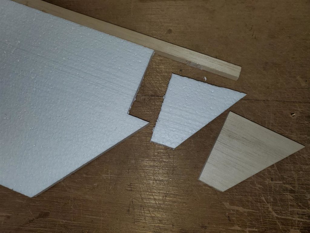
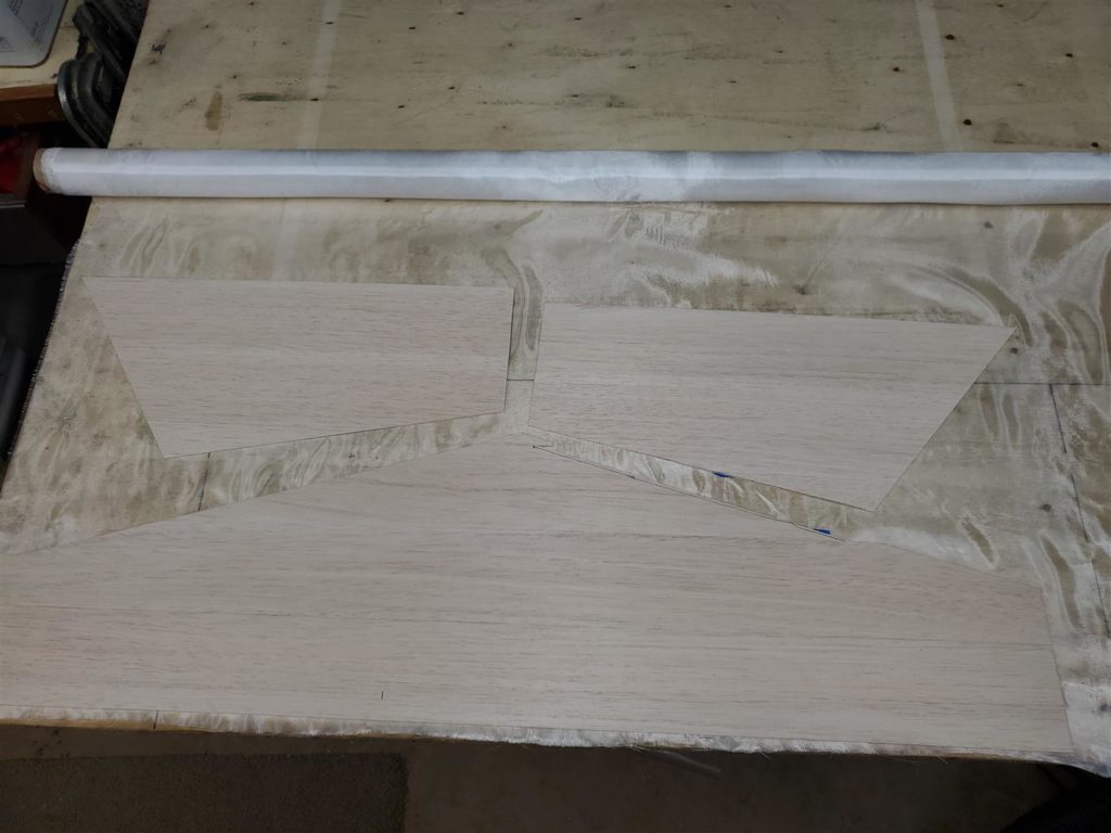
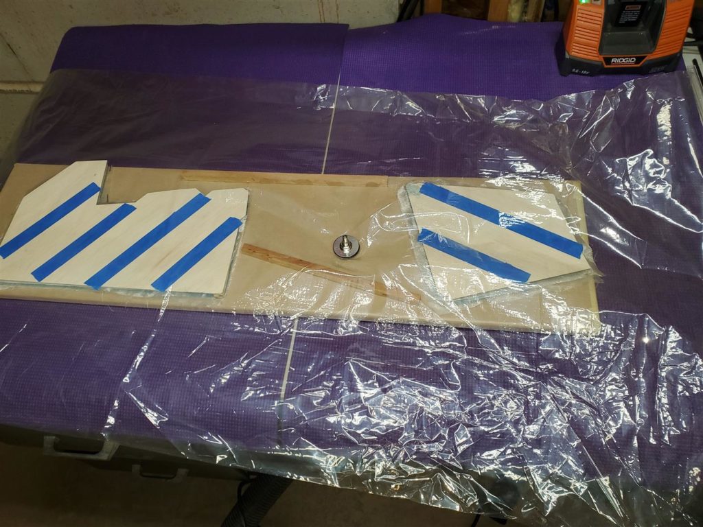
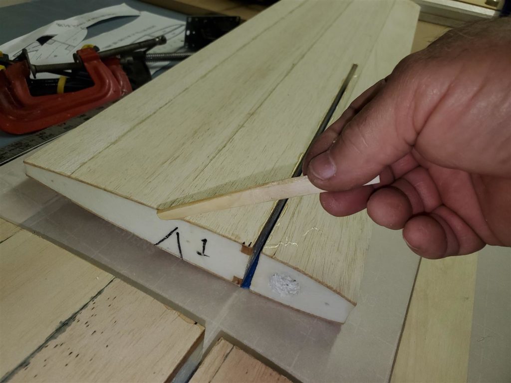
The sheets are then cut into oversized shapes for sheeting. The leading edge wood is also 3/8″ thick. Notice the wood block for the control horn attachment.
The wood pieces are attached to the foam with a few small dabs of 5 minute epoxy.
Tape can be used to hold them tight to the foam until the epoxy sets.
1/16″ thick balsa sheets are taped together and cut to rough shape for covering the parts. Grain direction is used to add strength.
The rudder and vertical stabilizer are sheeted with the grain at 45 degrees to add strenght in both directions.
A
.75 ounce fiberglass cloth is rough cut to fit the balsa sheeting.
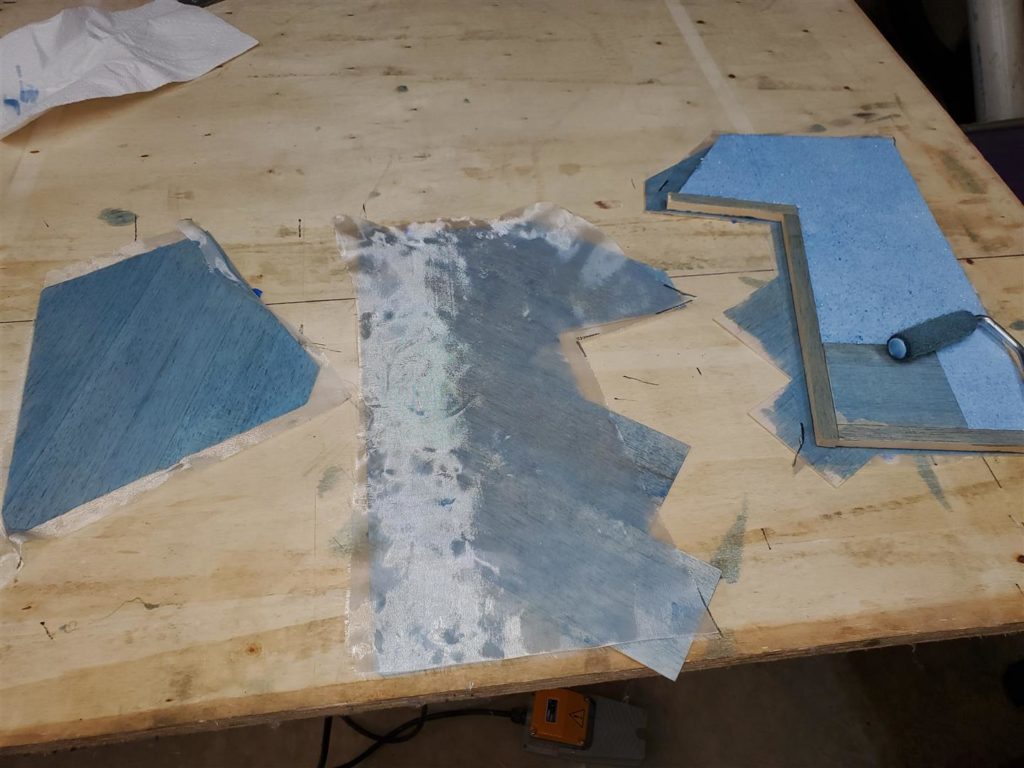
Epoxy is mixed and applied the same as the wings were sheeted.
I need to try and use less epoxy. Mike says it is too thick if the color shows so dark.
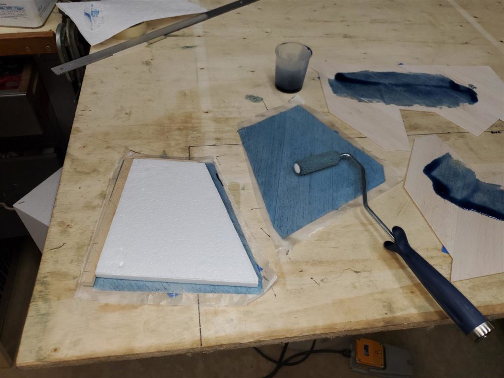
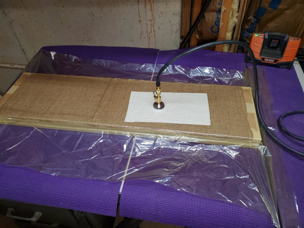
The parts are ready for the vacuum bag.
Several pieces of hardwood are placed between and at the ends of the parts to keep the vacuum from collapsing the foam. The wood is about a 1/16″ or less than the thickness of the finished part.
Notice the platens are still taped around the edges to keep the bag from sucking between them.
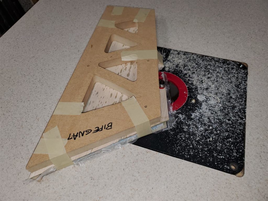
Now the parts are shaped on the router table. Notice all the foam dust on the table. I failed to close the access door after adjusting the router. So the vacuum did not work so well.
The areas where the tape is holding is moved to allow the entire part to be trimmed. Be careful to not allow the template to move while moving the tape. Blue tape can be used instead of the yellow tape.
The holes to make the lightening holes are drilled. I use a paddle bit. Be careful to stay in the middle of the cutout area. I drill almost though from the top and turn the part over and finish the hole to reduce tearout.
Elevators ready for edging.
Horizontal stabilizer ready too. I will get back to them later for edging and finishing. I need to work on the wings.
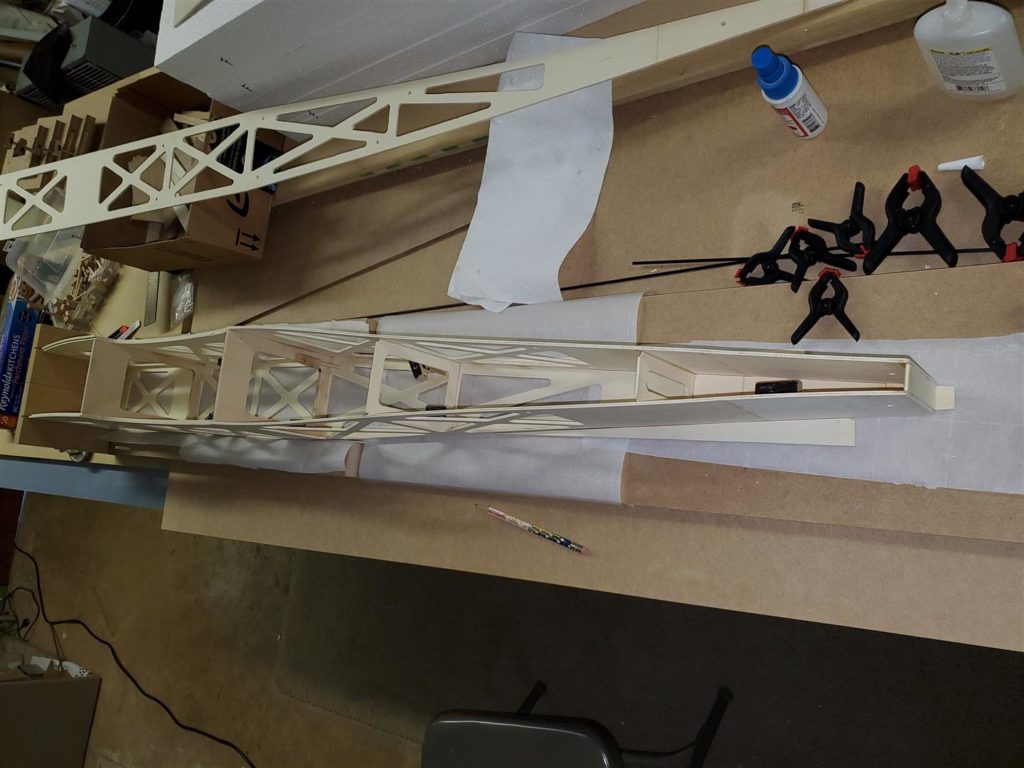
Wings
I have had the wings sheeted for a while. The wings will be one piece wings like the old Hog Bipe.
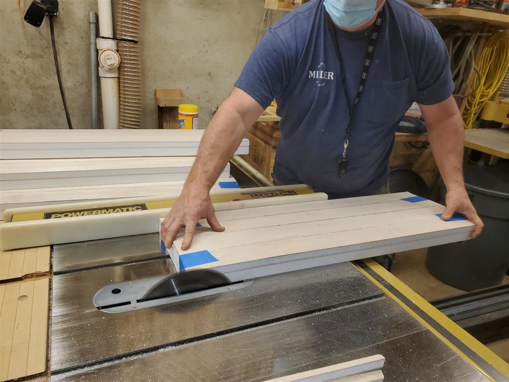
I took the wings to Mike’s shop for trimming and cutting slots for the joiner. His equipment is much nicer than mine and the cuts will be square and smooth.
The hand held vacuum hose really helps reduce foam gnats.
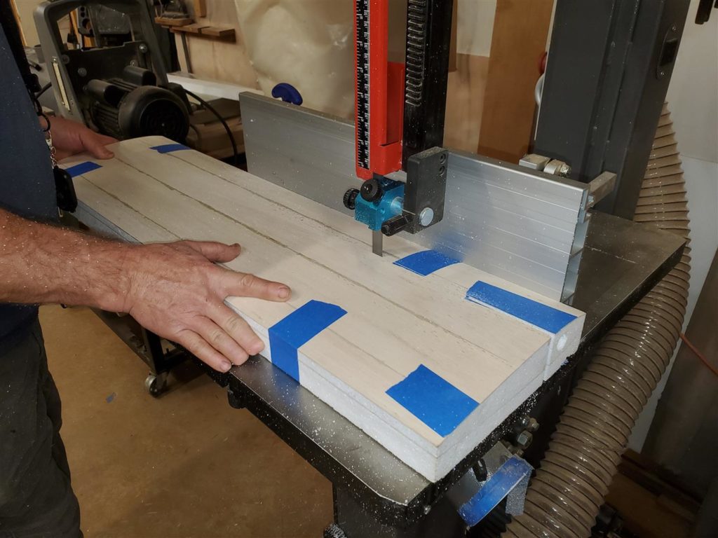
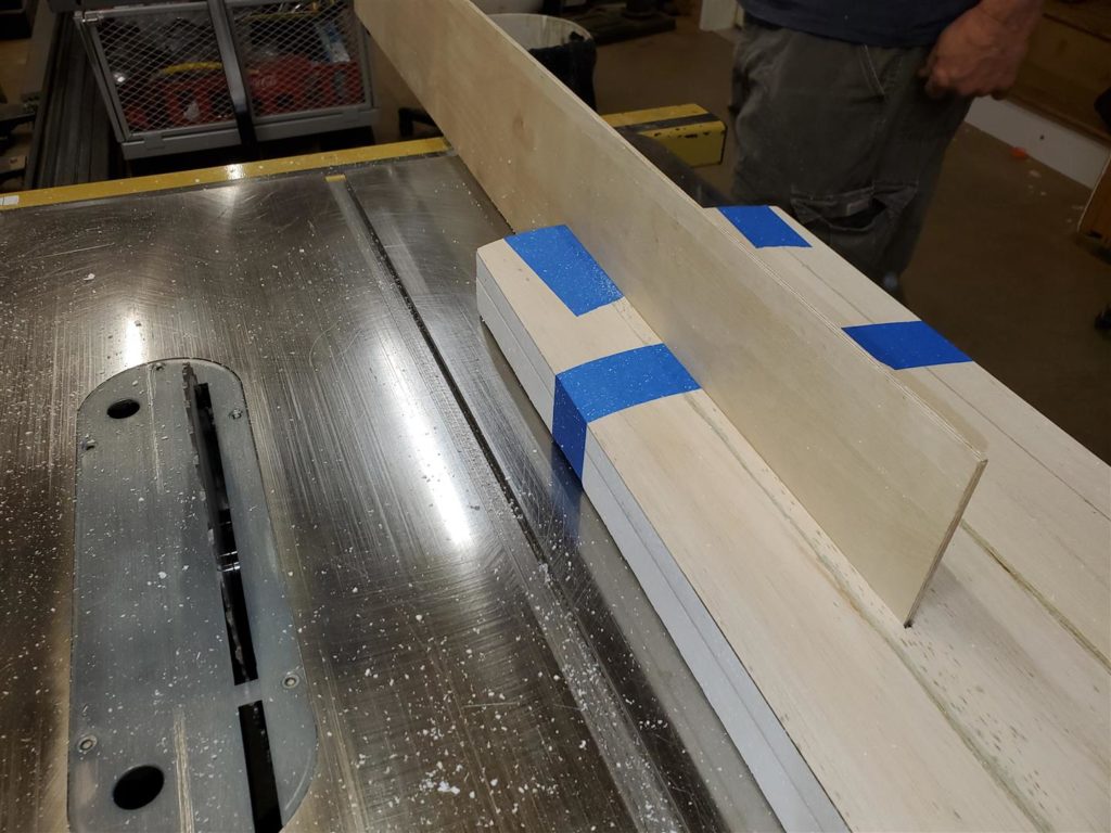
A tight fitting groove is cut into each wing half to accept the 3/16″ plywood joiner.
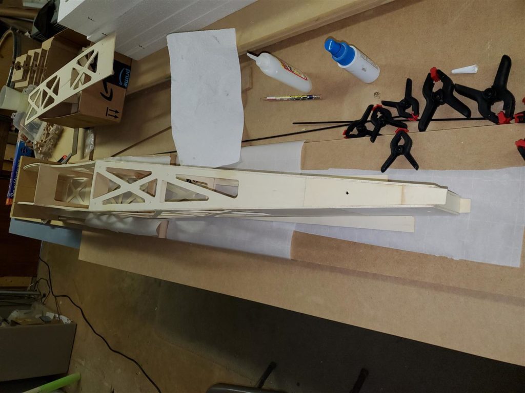
That is a nice square and snug fit.
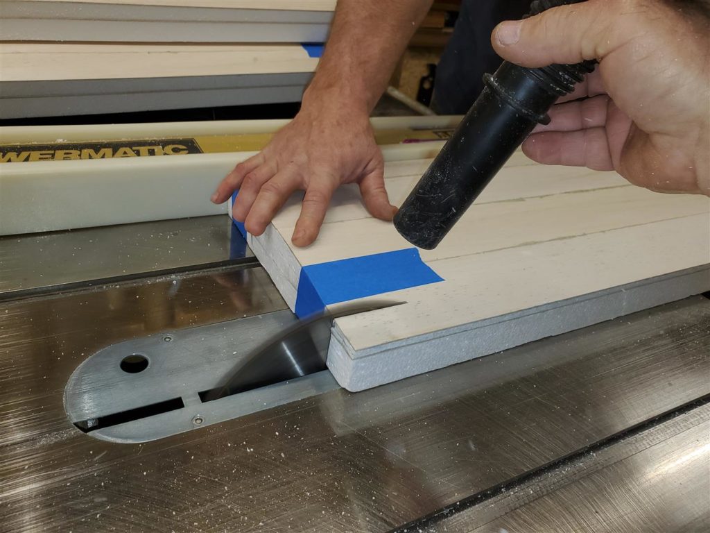
The root ends are cut on the tablesaw to make them square to the leading and trailing edges. Take care to only cut joiner slots into the root ends of the wing. Notice the joiner slot is right against the 1/4″ balsa spars.
I used 30 minute epoxy to glue in the joiners. I did not use micro-balloons.
Tape holds everything together while the epoxy cures. The wing is supported on a large flat surface with waxed paper or parchment paper to keep it from gluing to the table.
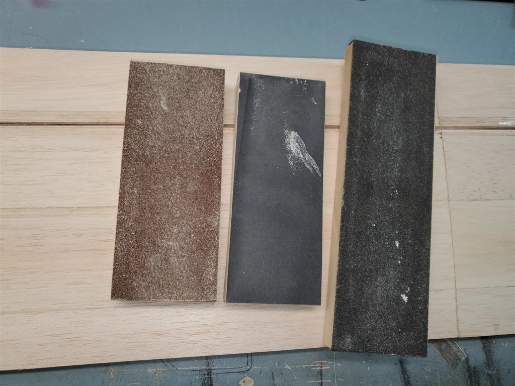
I made some 80 grit and 220 grit sanding blocks to smooth the balsa and level the plywood joiners. Be careful with the 80 grit while sanding plywood flush. It will scratch the balsa deeply and quickly.
Wing lightening hole templates were laid out next.
Keep in mind there must be enough meat left to mount the servos and the cabanes. I forgot about the cabanes and had to go back and fix the template before I used it.
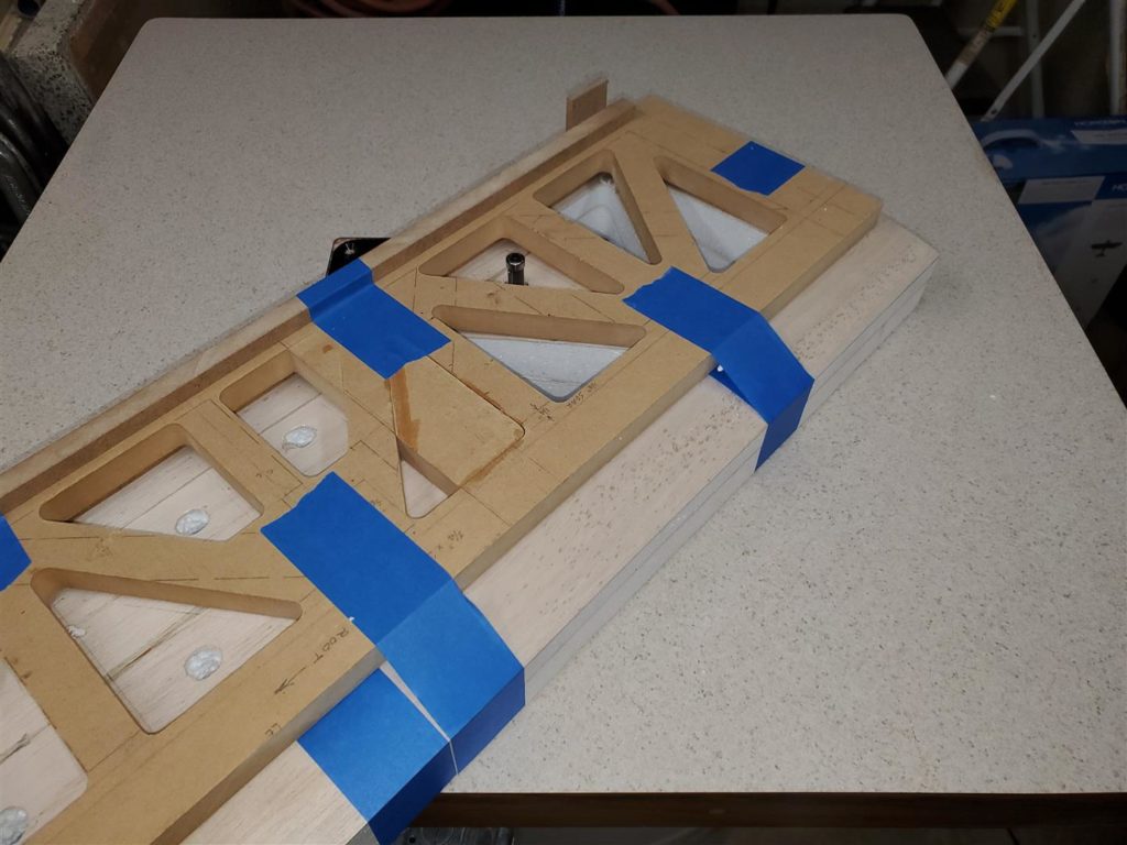
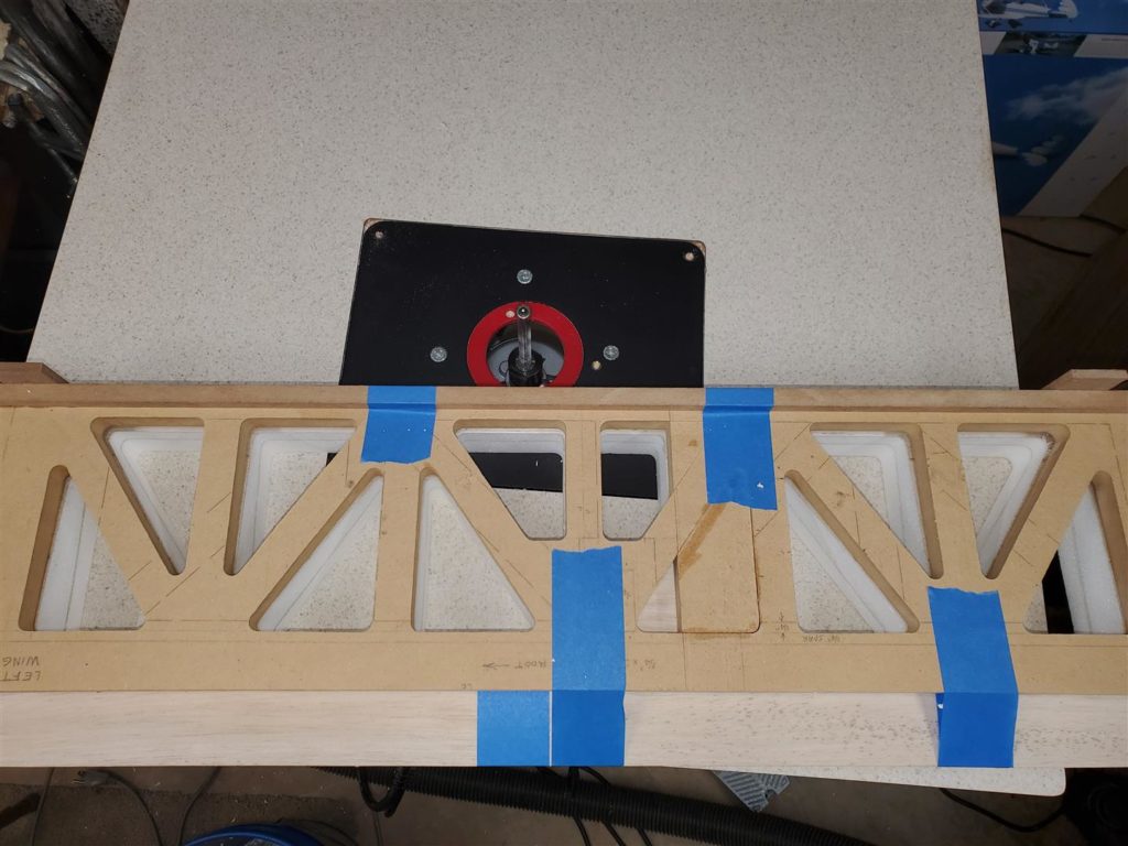
The holes are then routered out.
This is the completed and repaired template. I attached some guides on each end that snug up to the trailing edge of the wing.
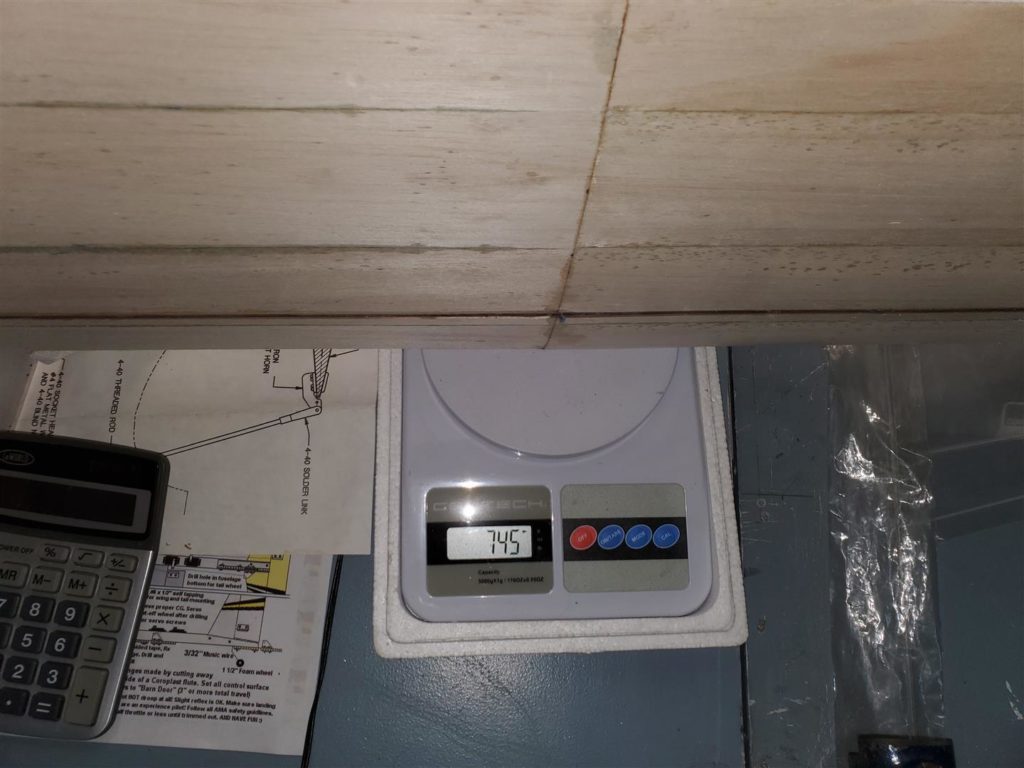
The wing weighs in at 745 grams before the lightening holes are installed.
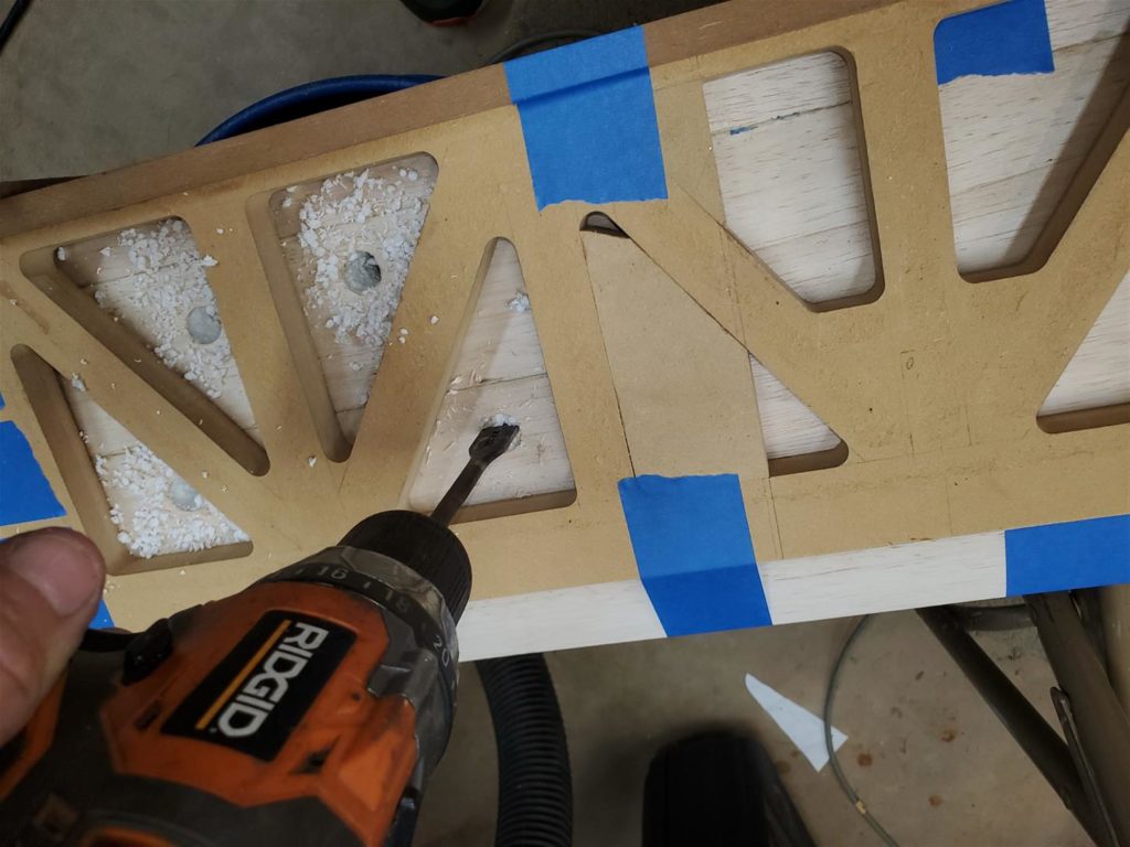
Drilling 5/8″ holes for the 1/2″ router bit.
Notice the glued in section of the template. The small hole left will not be cut into the wing.
Blue tape holds the template well. It must not move while the holes are cut. Place the tape strategically to avoid having to cut it with the router bit.
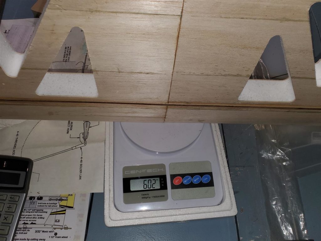
The wing weighs in at 602 grams after the holes are cut. That is a savings of 5 ounces per win which is definitely worth the effort.
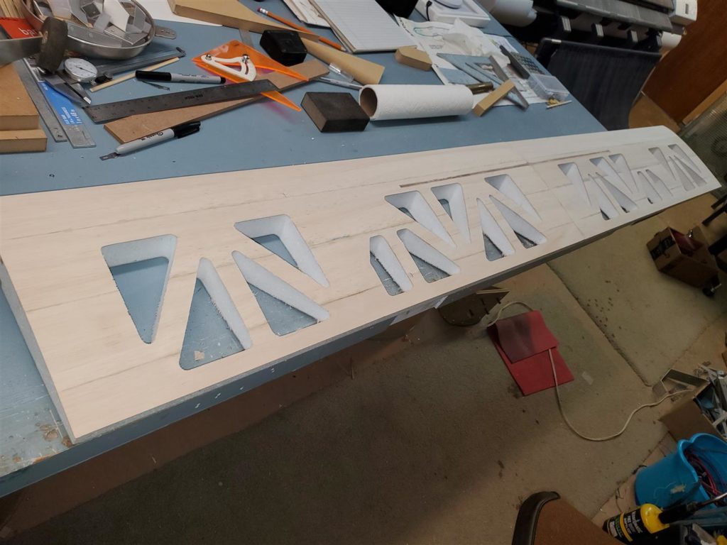
A The wing with lightening holes finished.
3/4″ triangle should be adequate for the wing leading edges.
1/2″ triangle should work for the wing trailing edges.
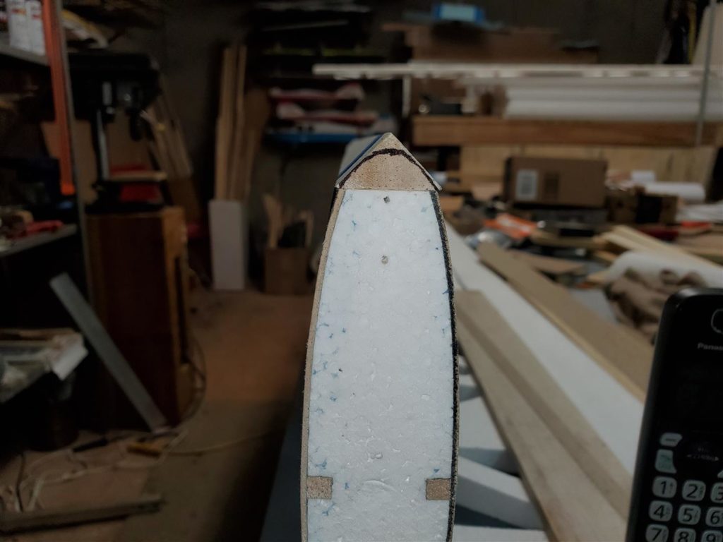
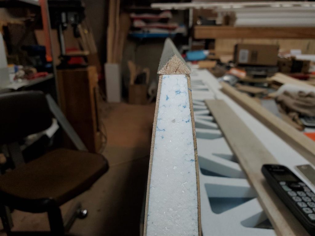
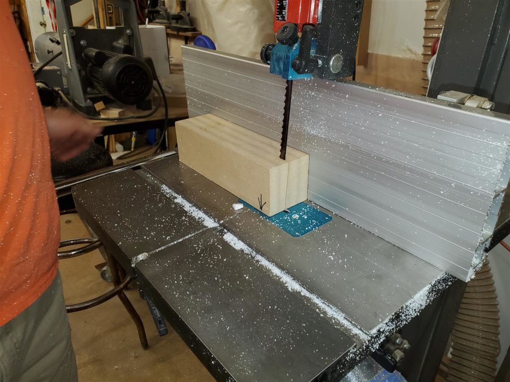
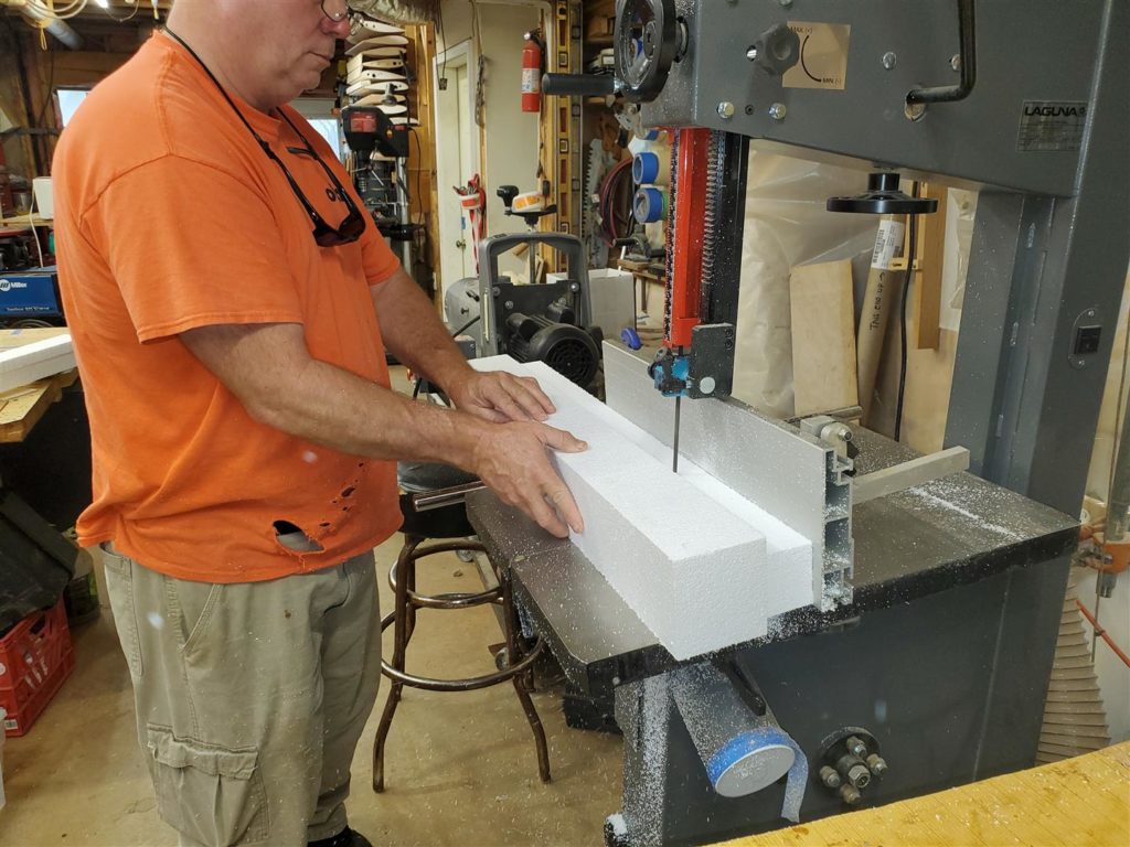
Ailerons will be constructed just as the wings were. They will need a foam core. So I visited Mike’s shop again so he could cut the foam on his nice bandsaw. My bandsaw is not near as nice and I would have to construct a fence to make these cuts.
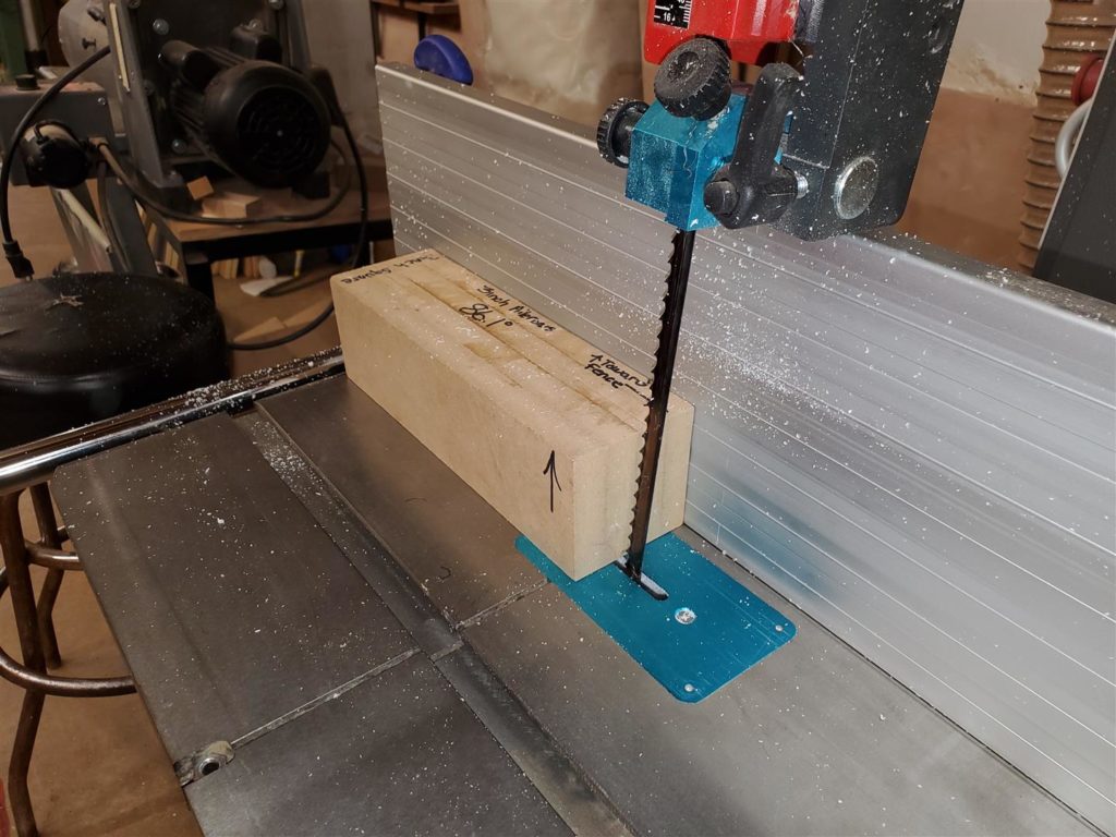
Mike also already had a template block that makes it easy to set up his saw.
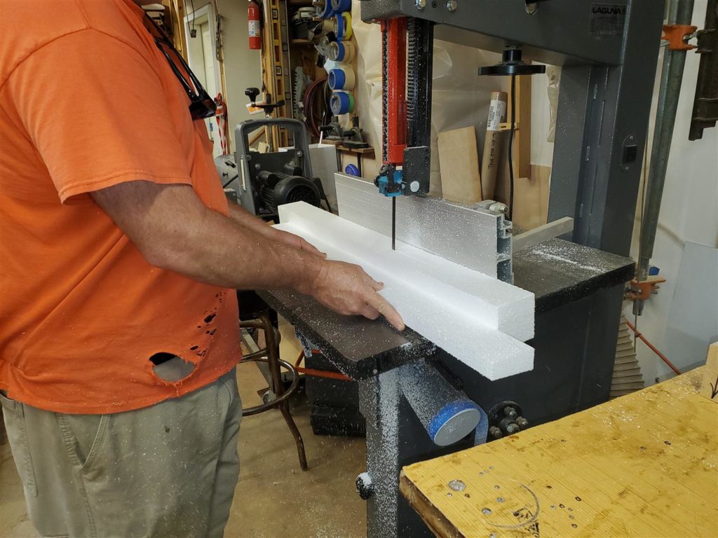
The block of foam Mike is pushing is an extra piece to hold even pressure on the part being cut. The secret to cutting the ailerons is to start with a 3″ square block of foam longer than needed for the ailerons. The foam is flipped end to end and then rolled over to make the angled cuts. This creates the shape of the aileron.
Extreme care to keep firm, even pressure is important. If the foam is allowed to move away from the fence or table, the aileron foam will not be shaped uniformly.